
Vacuum apparatus

a vacuum apparatus and vacuum technology, applied in the field of vacuum apparatus, can solve the problems of difficult to remove dust, debris and dirt from floors, elderly people and the disabled can encounter difficulties in bending and sweeping, and large quantities of debris can accumulate, so as to achieve convenient, effective, and convenient removal of dirt and dust.

Active Publication Date: 2017-09-26
SWEEPOVAC
View PDF13 Cites 0 Cited by
  • Summary
  • Abstract
  • Description
  • Claims
  • Application Information

AI Technical Summary

Benefits of technology

The vacuum apparatus of this patent solves the problem of efficiently and effectively removing dirt and dust from areas in a cost-effective manner. It is suitable for commercial and industrial environments and for domestic use, especially kitchens. It is convenient, reliable, and easy to use, requiring only the user to brush the dirt towards the air inlet aperture while the vacuum can be activated without bending or discomfort. The invention is particularly useful for the elderly, disabled, and those with mobility problems. It is compact and self-contained and can be installed in confined spaces or retrofitted in multiple locations within a building without causing disruption or damage. Overall, the vacuum apparatus utilizes previously unutilized space and solves the problem of “clean, green” environments.

Problems solved by technology

Difficulties can be encountered in removing dust, debris and dirt from floors which are intensively used such as domestic floors and commercial floors.
For example, elderly people and the disabled can encounter difficulties in bending and sweeping when cleaning domestic floors manually while considerable quantities of debris can accumulate in industrial and retail environments such as the food preparation, hairdressing and wood / metalwork industries.
However, known vacuum cleaners suffer from a number of disadvantages.
For example, known portable vacuum cleaners can be cumbersome to use—especially in confined domestic spaces and can still present difficulties to mobility impaired users when lifting and manoeuvring the vacuum cleaners.
However, such vacuum systems are expensive to install and can still present difficulties in use—particularly to the mobility impaired.
Moreover, central vacuum systems are difficult and prohibitively expensive to retrofit whilst causing severe disruption during the retrofitting process.

Method used


Image

  • Vacuum apparatus
  • Vacuum apparatus
  • Vacuum apparatus

Examples


first embodiment

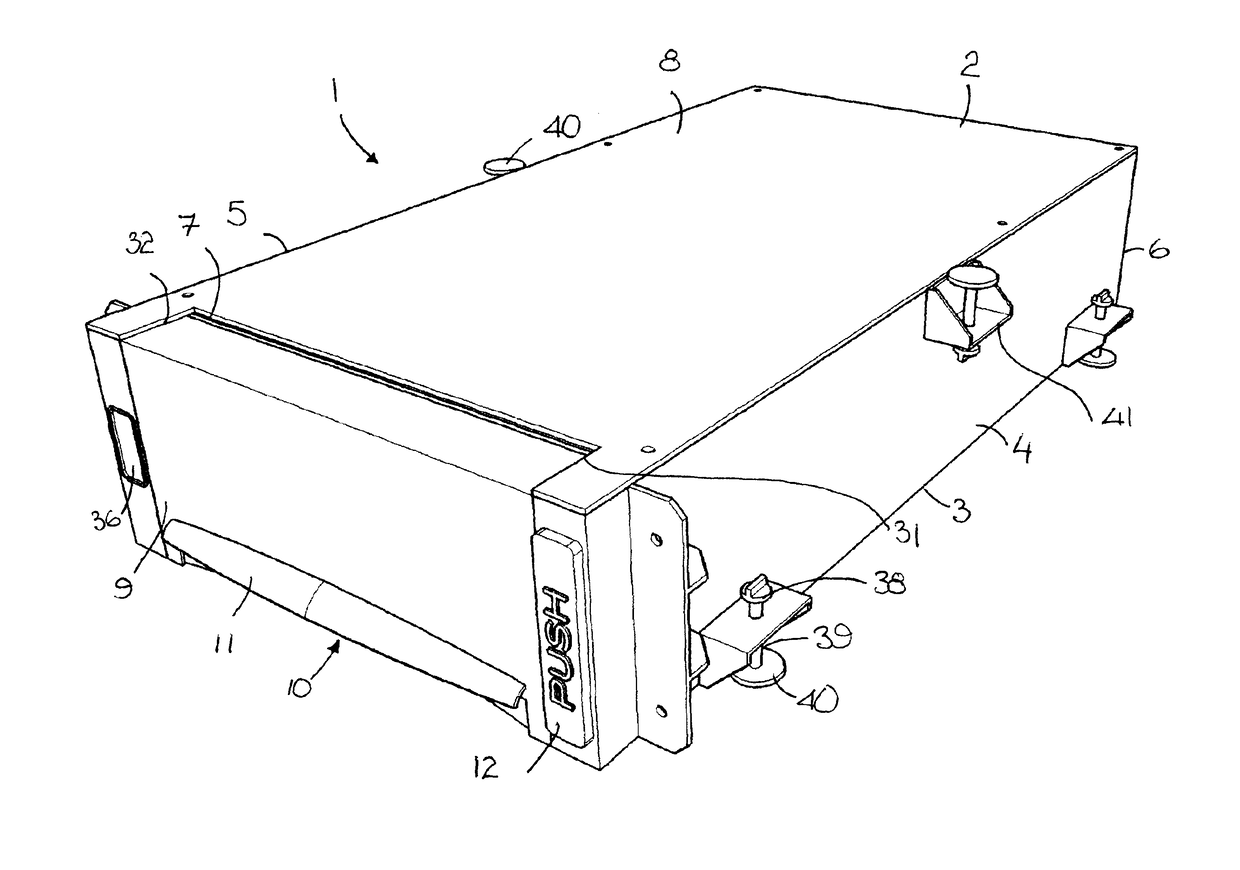
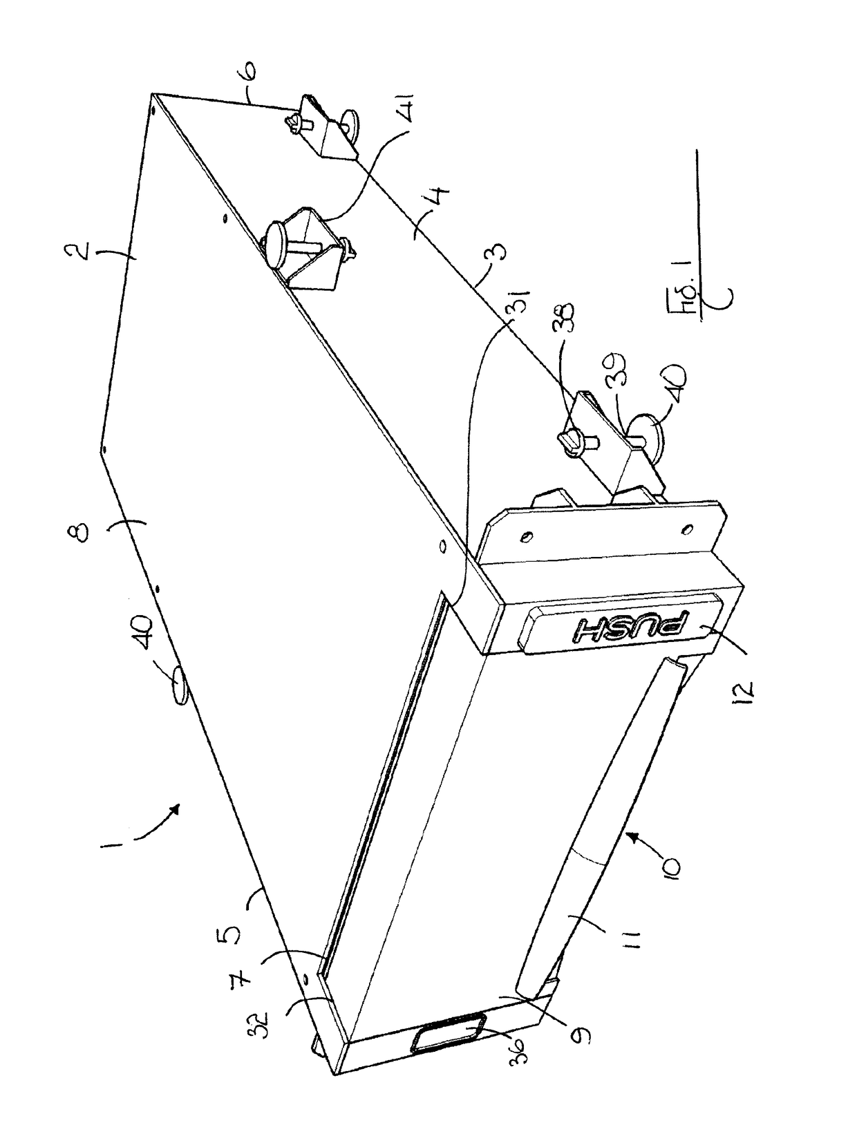
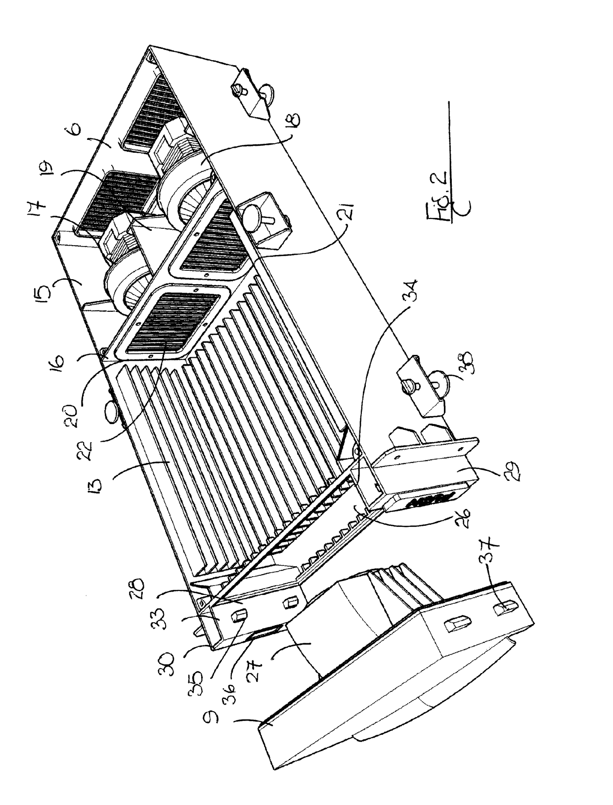
[0063]FIGS. 1 to 5 show a low-profile and compact self-contained or standalone vacuum apparatus of the invention generally indicated by the reference numeral 1 suitable for installation at floor-level so that dirt urged towards the vacuum apparatus can be sucked into and stored by the vacuum apparatus. In the following description, reference is made to a domestic installation and use of the vacuum apparatus. However, as indicated above, the vacuum apparatus of the invention is suitable for use in domestic, commercial and industrial environments. Moreover, the vacuum apparatus of the invention can be specifically adapted for use in such environments if desired.

[0064]As shown in FIGS. 1 to 5, the self-contained vacuum apparatus 1 is made up of an external shell or housing 2 having a bottom wall 3, first and second side walls 4,5 respectively upstanding from the bottom wall 3 and front and rear walls 6,7 respectively also upstanding from the bottom wall 3. The housing 2 is fitted with ...

second embodiment

[0077]FIGS. 6 to 15 show the self-contained vacuum apparatus 1 of the invention in which the vacuum apparatus 1 is provided with a single suction motor 17 in place of the twin suction motors 17,18 and a single air outlet aperture 23 in place of the pair of air outlet apertures 23,24 of FIGS. 1 to 5. Moreover, as shall be explained more fully below, in the present embodiment, the single air outlet aperture 23 is off-set with respect to the air inlet aperture 10 i.e. are not located on a single axis as shown in FIGS. 1 to 5 so that that the vacuum apparatus 1 vents air through the air outlet aperture 23 from its side. Like numerals indicate like parts.

[0078]As shown in FIGS. 6 to 15, the self-contained vacuum apparatus 1 is generally made up of a housing 2 having a removeable front head section 9 with an air inlet aperture 10 at floor or ground level, a storage cradle 13 in the housing 2 for holding a dustbag 14, a motor chamber 15 to the rear of the storage cradle for housing a singl...


PUM


Abstract

A self-contained vacuum apparatus having a housing with an air inlet aperture for receiving debris, a dustbag in the housing communicable with the air inlet for storing received debris, a suction motor communicable with the air inlet aperture for generating suction at the aperture to draw the debris into the dustbag, an air outlet aperture communicable with the suction motor to exhaust air from the vacuum apparatus, and an on / off switch for activating the vacuum apparatus, the vacuum apparatus being mountable in a cavity to locate the air inlet aperture adjacent a floor surface so that debris urged towards the air inlet aperture is drawn into the dustbag upon activation of the on / off switch.

Description

CROSS REFERENCE TO RELATED APPLICATION[0001]This application is a 35 USC 371 application of International PCT Patent Application No. PCT / IE2011 / 000065, filed on Dec. 7, 2011, and further claims priority to Ireland Patent IE S2010 / 0765, filed Dec. 7, 2010, and Ireland Patent IE S2011 / 0335, filed Jul. 28, 2011; the entire contents of which are hereby incorporated by reference herein in their entireties.INTRODUCTION[0002]This invention relates to a vacuum apparatus and more particularly to a self-contained vacuum apparatus for cleaning floors.BACKGROUND OF THE INVENTION[0003]Difficulties can be encountered in removing dust, debris and dirt from floors which are intensively used such as domestic floors and commercial floors. For example, elderly people and the disabled can encounter difficulties in bending and sweeping when cleaning domestic floors manually while considerable quantities of debris can accumulate in industrial and retail environments such as the food preparation, hairdres...

Claims


Application Information

Patent Timeline
Patent Type & Authority Patents(United States)
IPC IPC(8): A47L5/38A47L5/28A47L9/00A47L5/22A47L5/32
CPCA47L5/38A47L5/22A47L5/28A47L9/00A47L5/32
Inventor FINGLETON, HENRY JOSEPHCOSTELLO, DERMOT THOMAS
Owner SWEEPOVAC
Learn More