
Active vibration noise control apparatus

a technology of vibration noise and control apparatus, which is applied in the direction of active noise control, sound producing devices, musical instruments, etc., can solve the problem of weakened vibration noise reduction effect, and achieve the effect of low computational processing load

Inactive Publication Date: 2017-09-26
MITSUBISHI ELECTRIC CORP
View PDF22 Cites 0 Cited by
  • Summary
  • Abstract
  • Description
  • Claims
  • Application Information

AI Technical Summary

Benefits of technology

[0009]According to the active vibration noise control apparatus of the present invention, a frequency correction value of the control frequency is determined on the basis of the control signal, so that the mismatch between the control frequency and the actual vibration noise frequency can be reduced with a low computational processing load.

Problems solved by technology

Here, in a case where a frequency mismatch between an actual vibration noise frequency and the control frequency occurs owing to a measurement error and a signal delay, etc., of a rotation period sensor of rotating equipment, a problem arises in that a reduction effect on the vibration noise is weakened.

Method used


Image

  • Active vibration noise control apparatus
  • Active vibration noise control apparatus
  • Active vibration noise control apparatus

Examples


embodiment 1

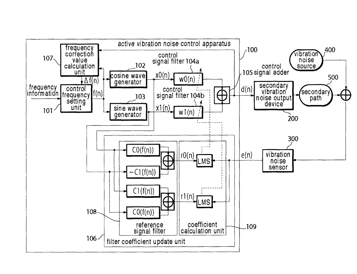
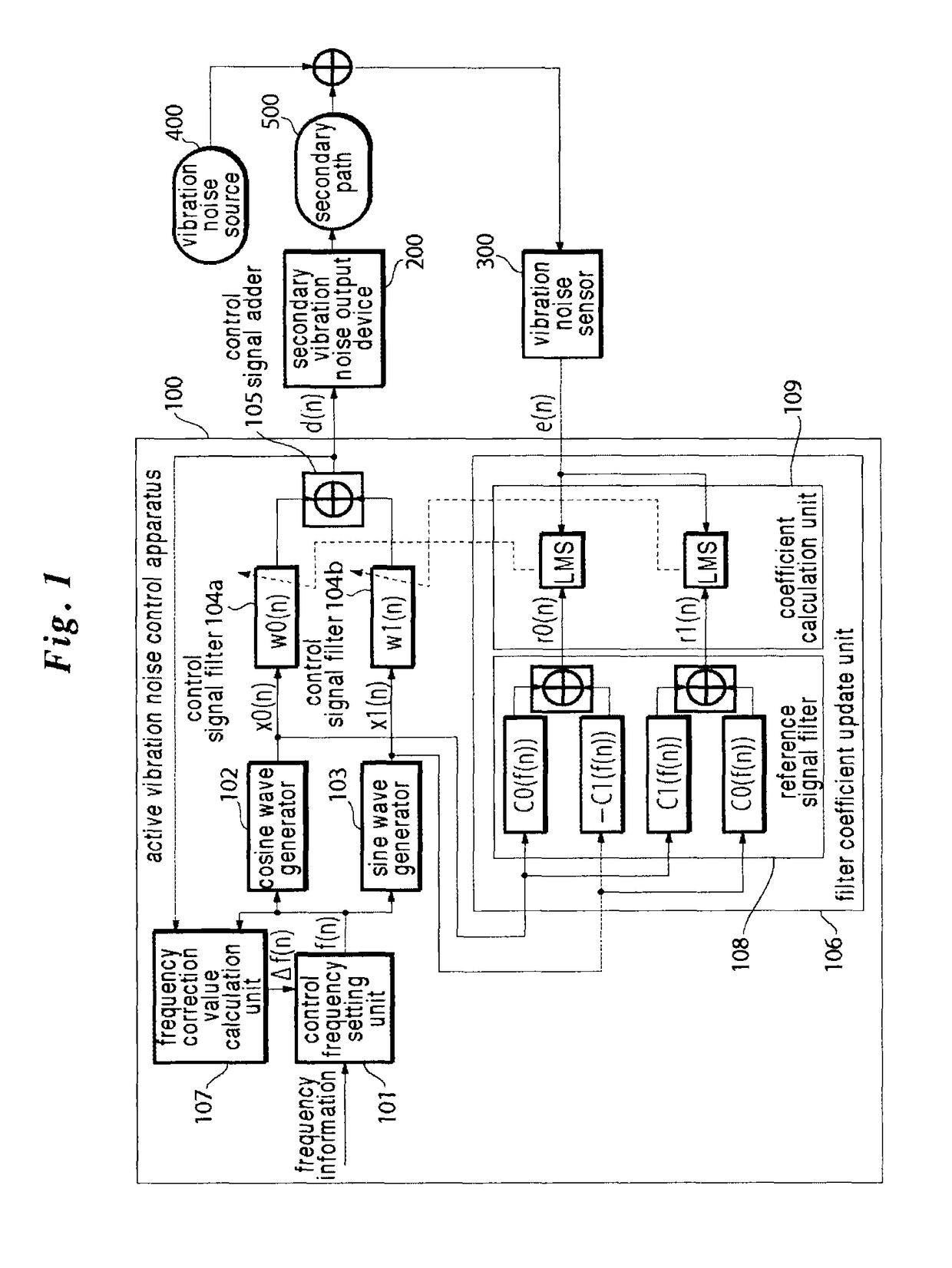
[0015]As shown in FIG. 1, an active vibration noise control apparatus 100 according to Embodiment 1 of the present invention is connected to a secondary vibration noise output device 200 and a vibration noise sensor 300 that are disposed outside. The active vibration noise control apparatus 100 receives frequency information on vibration noise from a vibration noise source 400 being a controlled object, and outputs a generated control signal based on the input frequency information.

[0016]For example, in the case where the vibration noise source is an automobile engine, the frequency information of the vibration noise can be obtained by such a method in which a rotational frequency of an engine is measured on the basis of the period of ignition pulses, and then constant multiplication of the rotational frequency is performed in accordance with the rotational order of the engine generating the target vibration noise. And, in the case of a fan driven by an electric motor, the frequency...

embodiment 2

[0058]The invention is applicable in a configuration in which the cosine wave signal x0(n) and the sine wave signal x1(n) that are sources for the control signal d(n) are not generated inside, but are input from the outside of an active vibration noise control apparatus. As an example of the configuration, an active vibration noise control apparatus according to Embodiment 2 of the present invention will be described.

[0059]In the following description, Embodiment 2 of the present invention will be described using figures. FIG. 4 is a block diagram of the active vibration noise control apparatus according to Embodiment 2 of the present invention. It is noted that parts common with or corresponding to those in Embodiment 1 are denoted by the same reference numerals as those in FIG. 1.

[0060]As shown in FIG. 4, the active vibration noise control apparatus 600 according to Embodiment 2 is connected to a cosine wave and sine wave generator 700 and the secondary vibration noise output devi...


PUM


Abstract

A first control signal filter to which a cosine wave oscillating at a control frequency is input; a second control signal filter to which a sine wave oscillating at the control frequency is input; a control signal adder for outputting a control signal generated by adding an output of the first control signal filter and an output of the second control signal filter; a filter coefficient update unit for updating filter coefficients of the first control signal filter and the second control signal filter; and a frequency correction value calculation unit for calculating a frequency correction value for correcting the control frequency on the basis of the control signal and the control frequency.

Description

TECHNICAL FIELD[0001]The invention relates to an active vibration noise control apparatus which reduces vibration noise by generating a control signal on the basis of a control frequency determined in accordance with a rotational period of rotating equipment.BACKGROUND ART[0002]As an apparatus for reducing vibration noise originated by rotating equipment such as a vehicle engine, an active vibration noise control apparatus using an adaptive notch filter is known. In such a conventional active vibration noise control apparatus, a control frequency is set to a vibration noise frequency identified by the rotational period of rotating equipment, and a control signal having an opposite phase of the vibration noise and having the control frequency is generated, and is output as a secondary vibration noise that is to be interfered with the vibration noise, so that the vibration noise is reduced.[0003]Here, in a case where a frequency mismatch between an actual vibration noise frequency and...

Claims


Application Information

Patent Timeline
Patent Type & Authority Patents(United States)
IPC IPC(8): G10K11/178
CPCG10K11/178G10K2210/1282G10K2210/3028G10K11/17823G10K11/17854G10K11/17855G10K11/17883
Inventor YANO, ATSUYOSHI
Owner MITSUBISHI ELECTRIC CORP
Learn More