
Storage system including encoder

a technology of encoder and encoder, applied in the field of storage system including encoder, can solve the problems of large data reduction, encoder and decoder which include neural networks, small amount of data loss, etc., and achieve the effect of low calculation processing load, low calculation processing load and high calculation processing load

Pending Publication Date: 2021-06-03
HITACHI LTD
View PDF7 Cites 0 Cited by
  • Summary
  • Abstract
  • Description
  • Claims
  • Application Information

AI Technical Summary

Benefits of technology

The invention aims to reduce the overall calculation processing load while minimizing data loss during compression and decompression. Complex data is compressed using a method that requires high calculation processing load, while simple data is compressed using a method that requires lower load. This results in a lower overall calculation processing load and allows for a small amount of data loss.

Problems solved by technology

Such an encoder and a decoder have a small amount of data loss due to lossy compression and a large amount of data reduction (higher compression ratio) than manually designed encoders and decoders.
However, the encoder and the decoder which include a neural network have a high calculation processing load in compression and decompression.
Accordingly, a lot of time may be required for the compression and decompression processing, an expensive calculation resource such as a central processing unit (CPU) or a graphics processing unit (GPU) having a large number of cores may be required, or power consumption may increase.
Therefore, the calculation cost required for the compression and the decompression may increase, and the system cost as a sum of the calculation cost and the data retention cost may not be reduced.

Method used


Image

  • Storage system including encoder
  • Storage system including encoder
  • Storage system including encoder

Examples


first embodiment

(1-1) System Configuration

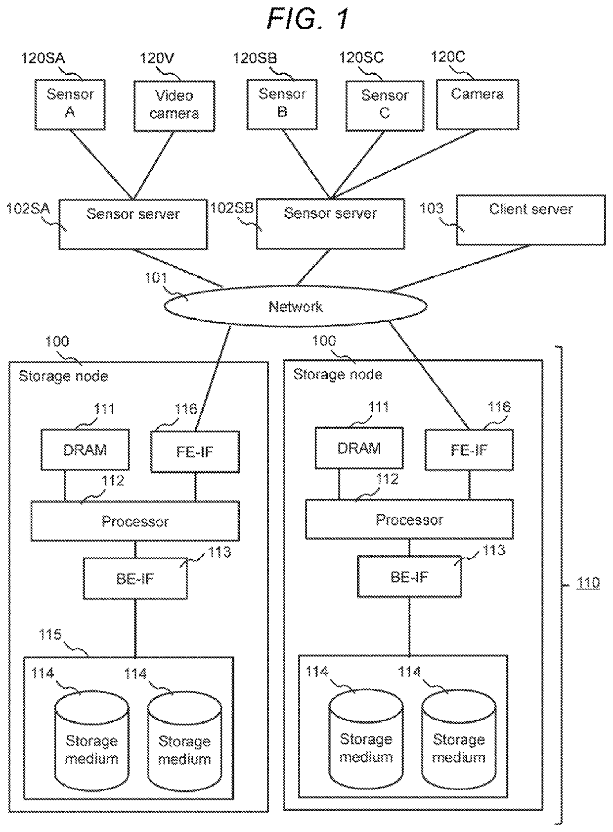
[0035]First, a system configuration according to the present embodiment will be described with reference to FIG. 1.

[0036]FIG. 1 shows the system configuration according to the first embodiment.

[0037]A data source 102, such as a plurality of (or one) sensor servers 102S, and a client server 103 are connected via network 101 to a storage system 110 including a plurality of (or one) storage nodes 100.

[0038]Each of the storage nodes 100 includes a DRAM 111 serving as a primary storage area, a processor 112 for executing various processing in accordance with software, a back-end interface device (BE-IF) 113 connected to one or more storage media 114, a persistent storage device 115 (for example, the one or more storage media 114) serving as a secondary storage area, and a front-end interface (FE-IF) 116 connected to the network 101. The BE-IF 113 and the FE-IF 116 are examples of the interface device. The DRAM 111 is an example of the memory. The DRAM 111, the B...

second embodiment

[0135]Next, a second embodiment will be described. In this case, the differences from the first embodiment will be mainly described, and the points common with the first embodiment will be omitted or simplified.

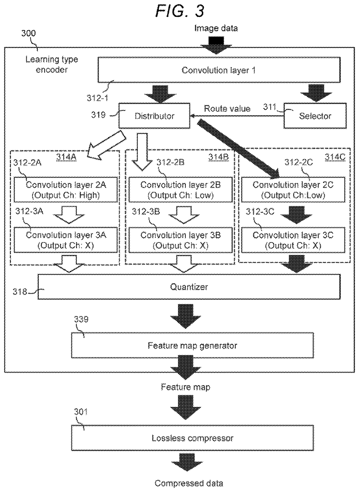
[0136]In the first embodiment, the plurality of compression routes 314 (the plurality of decompression routes 414) and the selector 311 (the selector 411) for selecting a compression route 314 (a decompression route 414) in the encoder 300 (or the decoder 400) are included. An optimal compression route (partial feature map) is selected for each partial image (partial feature map) to be a target, and compression (or decompression) is performed.

[0137]In contrast, in the second embodiment, the processing load can be reduced (in other words, the processing speed can be increased) by setting the number of channels in the convolution operation (transposed convolution operation), the kernel amount in the convolution operation, or the like to an optimal value for each partial image a...


PUM


Abstract

To reduce a calculation processing load as a whole while realizing a small amount of data loss for at least one of compression and decompression. For each of a plurality of pieces of data, a storage system determines a compression operation scale of the data based on a feature of the data, executes a lossy compression operation according to the determined compression operation scale to covert the data into encoded data, and stores the encoded data or compressed data thereof into a storage device.

Description

BACKGROUND OF THE INVENTION1. Field of the Invention[0001]The present invention generally relates to storage control including compression.2. Description of the Related Art[0002]A storage system for reducing the amount of data has been known (for example, JP-A-2007-199891). In general, this type of storage system reduces the amount of data by compression. As one of existing compression methods, a method of converting a character string having a high appearance frequency into a dictionary in a predetermined block unit and replacing the character string with a code having a smaller size, like a run-length method, has been known.[0003]In recent years, a learning type lossy compression technology, in addition to such a general-purpose data compression method, has appeared.[0004]For example, it is possible to create an encoder and a decoder specialized in compression and decompression of data in the same field as learning data by constructing an encoder and a decoder which include a neur...

Claims


Application Information

Patent Timeline
Patent Type & Authority Applications(United States)
IPC IPC(8): G06F16/174G06N3/08
CPCG06F16/1744G06N3/08G06N3/047G06N3/045
Inventor SUZUKI, AKIFUMINARUKO, TAKAHIROAKUTSU, HIROAKI
Owner HITACHI LTD
Learn More