
Clock correction method and circuit utilizing training sequence to correct oscillator output, and reference clock generation method and circuit utilizing training sequence to generate reference clock

a clock correction and oscillator technology, applied in the field of clock correction, can solve the problems of system performance degradation, crystal oscillator integrated in to a system chip cannot provide a precise reference clock, additional costs and space, etc., and achieve the effect of reducing/eliminating the effects of chip temperature, no additional circuit area, and manufacturing cos

Active Publication Date: 2017-10-03
SILICON MOTION INC (TW)
View PDF9 Cites 2 Cited by
  • Summary
  • Abstract
  • Description
  • Claims
  • Application Information

AI Technical Summary

Benefits of technology

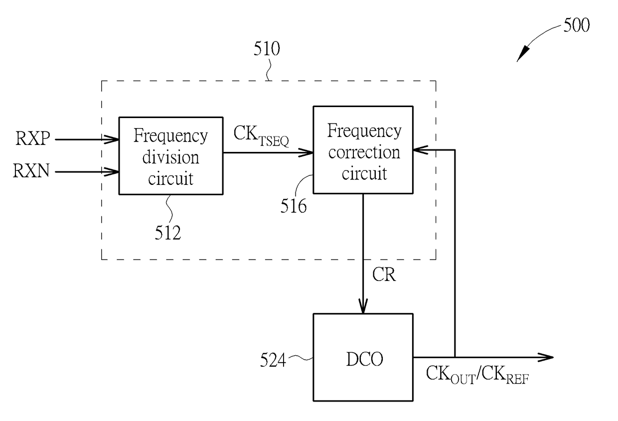
[0012]By utilizing periodic properties of an equalization training sequence to correct an output clock of an oscillator, the proposed clock correction mechanism / reference clock generation mechanism may reduce / eliminate effects caused by chip temperature and process variations with almost no additional circuit area and manufacturing cost.

Problems solved by technology

A conventional universal serial bus (USB) 3.0 system has to use an external quartz crystal oscillator to provide precise reference clock, which results in additional costs and spaces.
However, in a conventional crystal-less USB system, a crystal oscillator integrated in to a system chip cannot provide a precise reference clock due to temperature and process variations.
This results in system performance degradation.

Method used


Image

  • Clock correction method and circuit utilizing training sequence to correct oscillator output, and reference clock generation method and circuit utilizing training sequence to generate reference clock
  • Clock correction method and circuit utilizing training sequence to correct oscillator output, and reference clock generation method and circuit utilizing training sequence to generate reference clock
  • Clock correction method and circuit utilizing training sequence to correct oscillator output, and reference clock generation method and circuit utilizing training sequence to generate reference clock

Examples


Embodiment Construction

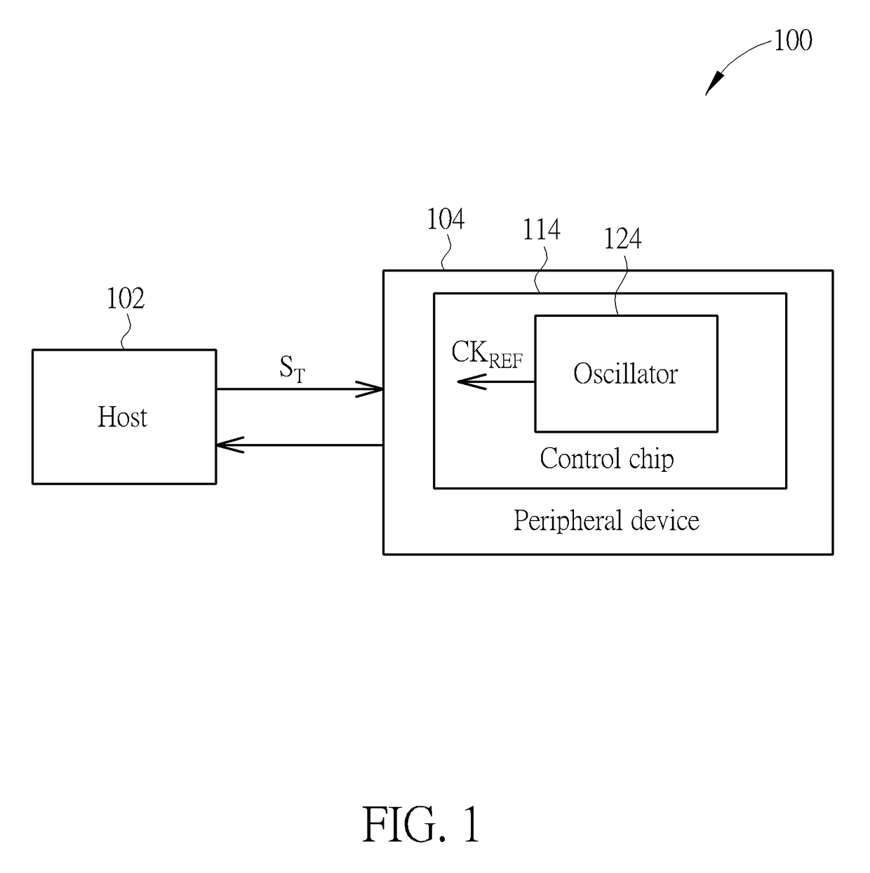
[0020]FIG. 1 is a diagram illustrating an exemplary data transmission system according to an embodiment of the present invention. The data transmission system 100 may include a host (e.g. a personal computer) 102 and a peripheral device 104, wherein the host 102 and the peripheral device 104 perform data transmission and communicate with each other according to a communication protocol. By way of example but not limitation, the communication protocol may include a universal serial bus (USB) protocol (e.g. USB 3.0 protocol), and the peripheral device 104 may be implemented by an electronic apparatus having USB port(s).

[0021]In this embodiment, the peripheral device 104 may include a control chip 114, which may include an oscillator (e.g. a digital-controlled oscillator (DCO)) 124 integrated therein. The oscillator 124 may generate a reference clock CKREF to be used as a reference clock for data transmission and reception between the host 102 and the peripheral device 104. In order to...


PUM


Abstract

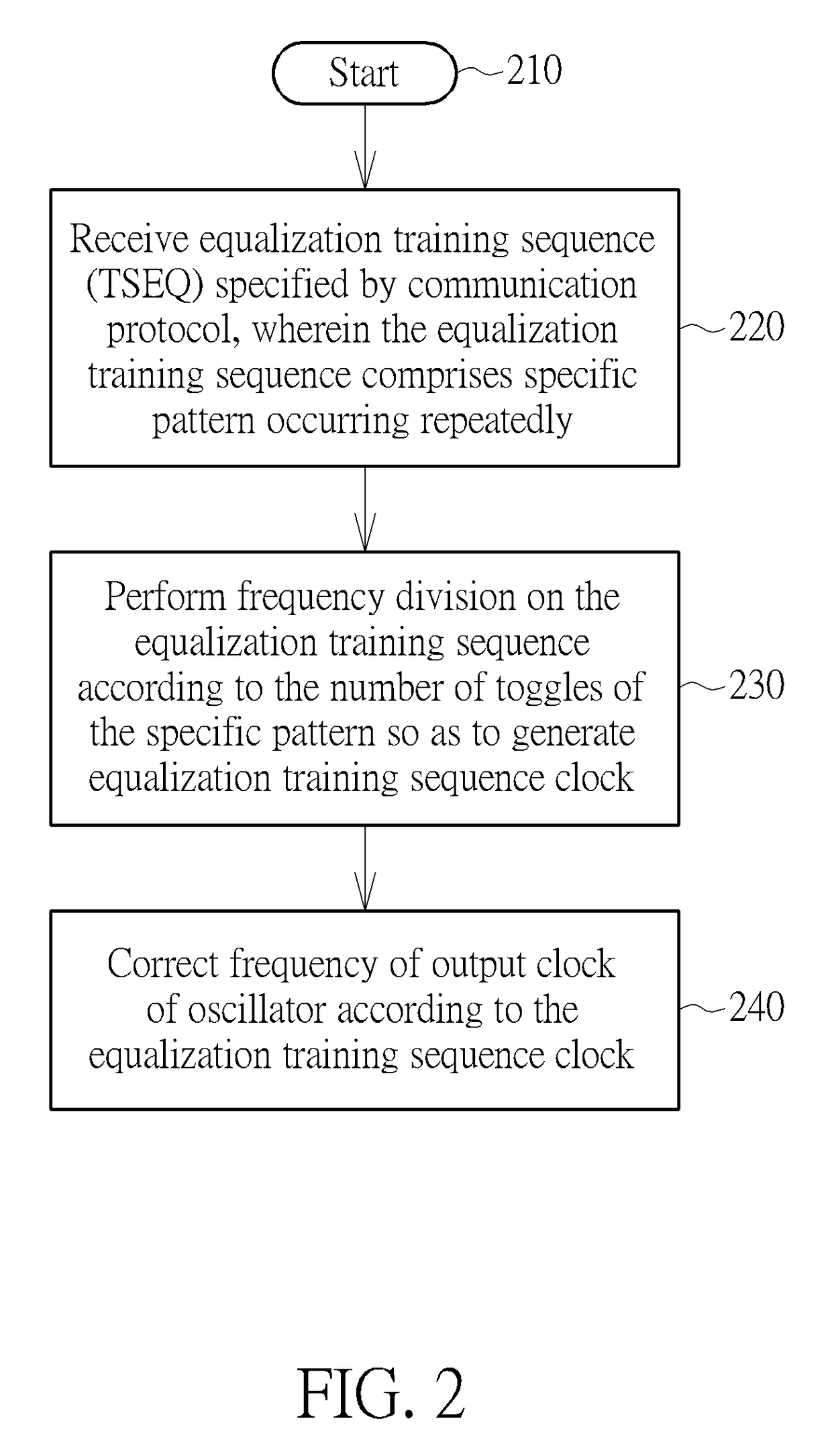
A clock correction method is provided. The clock correction method includes the following steps: receiving an equalization training sequence specified by a communication protocol, wherein the equalization training sequence includes a specific pattern occurring repeatedly; performing frequency division on the equalization training sequence according to a number of toggles of the specific pattern so as to generate an equalization training sequence clock; and correcting a frequency of an output clock of an oscillator according to the equalization training sequence clock.

Description

BACKGROUND OF THE INVENTION[0001]1. Field of the Invention[0002]The disclosed embodiments of the present invention relate to clock correction, and more particularly, to a clock correction method utilizing a training sequence used for communication link training to correct a frequency of an output clock of an oscillator, and related method for generating a reference clock, clock correction circuit and circuit for generating a reference clock.[0003]2. Description of the Prior Art[0004]A conventional universal serial bus (USB) 3.0 system has to use an external quartz crystal oscillator to provide precise reference clock, which results in additional costs and spaces. In order to save costs and spaces, the manufacturer integrates an oscillator into a system chip to realize a crystal-less design. However, in a conventional crystal-less USB system, a crystal oscillator integrated in to a system chip cannot provide a precise reference clock due to temperature and process variations. This re...

Claims


Application Information

Patent Timeline
Patent Type & Authority Patents(United States)
IPC IPC(8): H04L7/033H04L27/01H04L1/24
CPCH04L27/01H04L1/242H04L7/033H03K5/135G06F13/40H04L7/0331H04L7/041H04L25/03
Inventor LIN, YAIN-REU
Owner SILICON MOTION INC (TW)
Learn More