Optical ranging sensor and electronic equipment

a technology electronic equipment, which is applied in the direction of distance measurement, height/levelling measurement, instruments, etc., can solve the problems of increasing the response time of optical ranging sensor, increasing the error of a value determined center of gravity, and increasing the power consumption therein, so as to reduce the size of the whole optical ranging sensor and reduce the manufacturing cost. , the effect of reducing the size of the chip

Active Publication Date: 2013-03-05
SHARP KK +1
View PDF25 Cites 24 Cited by
  • Summary
  • Abstract
  • Description
  • Claims
  • Application Information

AI Technical Summary

Benefits of technology

[0046]As is apparent from the above, in the optical ranging sensor of the invention, regarding the effective light receiving part of the light receiving unit on which reflected light of a light beam projected from the light emitting unit and reflected by an object to be measured is incident, the size of the effective light receiving part in the second direction orthogonal to the first direction, in which direction the light spot moves as the object to be measured moves in the direction of the optical axis of the light emitting unit, is set to be not less than the radius and not more than the diameter of the light spot. Thus, it is possible to reduce a size of a chip in which the light receiving unit is installed, while ensuring the size sufficient for determination of a center of gravity of the light spot, and hence to reduce a size of the whole optical ranging sensor and the manufacturing cost.
[0047]Furthermore, when the whole light receiving unit forms the effective light receiving part, or when areas except the effective light receiving part in the light receiving unit are blocked from functioning as a light receiving part for ranging, it is possible to eliminate unnecessary signals from the areas other than the effective light receiving part. This will reduce processing time in the processing circuit unit and thus reduces response time of the optical ranging sensor and power consumption. In addition, the elimination of the unnecessary signals increases the S / N ratio in the signal processing and improves performance.
[0048]Also, the electronic equipment of the invention includes the optical ranging sensor that can fulfill small size, high performance, low power consumption, high-speed response, and low cost. Thus, a distance to an object to be measured by the electronic equipment can accurately and quickly be measured. Increase in size, power consumption, and cost caused by the installation of the optical ranging sensor can be minimized.

Problems solved by technology

This causes a problem in that increased time required for the calculation brings about increase in response time of the optical ranging sensor and increase in power consumption therein.
Besides, the data from the unnecessary portion of the light receiving unit makes a noise in the determination of the center of gravity of the light spot 4, which noise results in decrease in S / N and increase in an error of a value of the determined center of gravity.
As a result, there is caused a problem of deterioration in performance of the optical ranging sensor.

Method used


Image

  • Optical ranging sensor and electronic equipment
  • Optical ranging sensor and electronic equipment
  • Optical ranging sensor and electronic equipment

Examples


Embodiment Construction

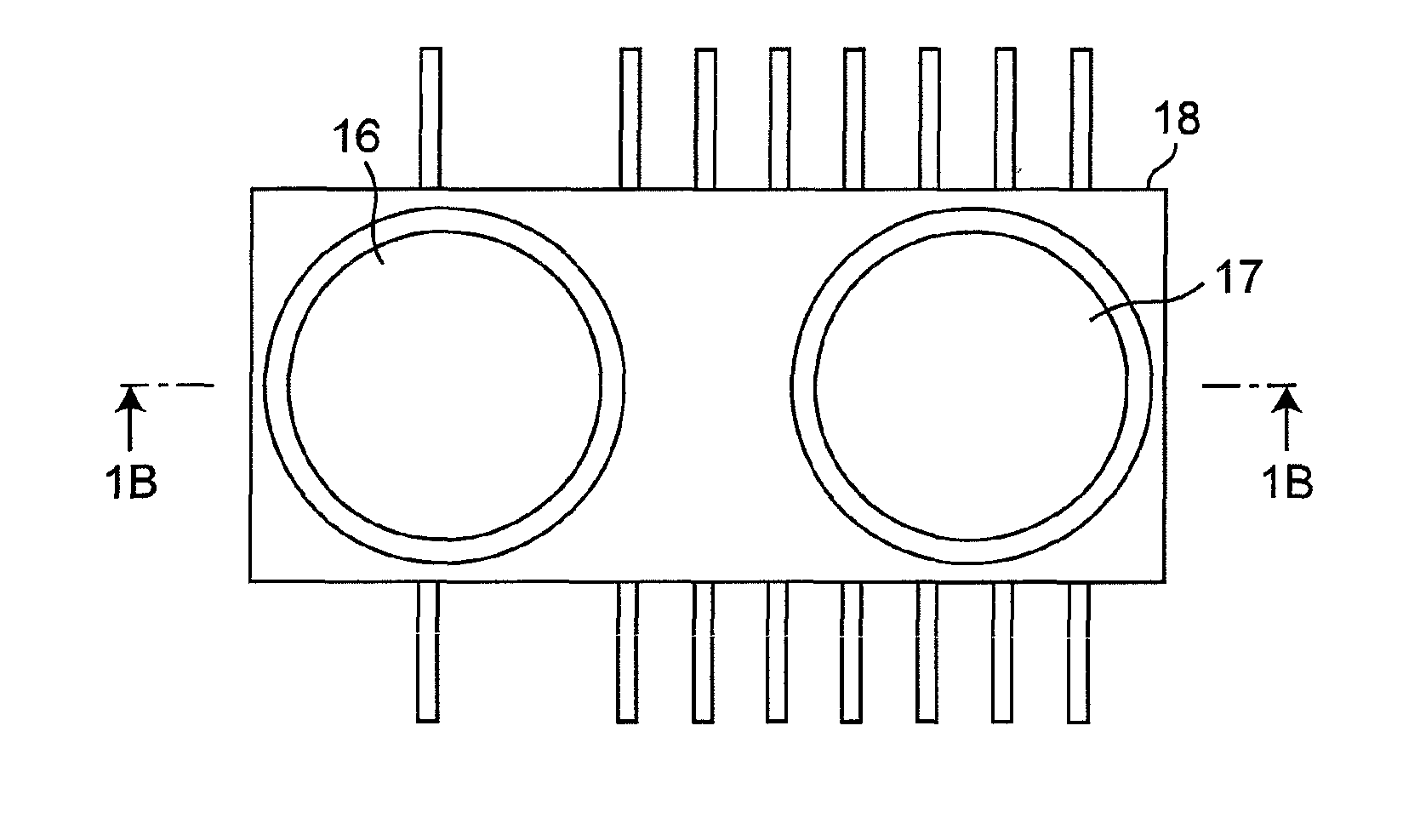
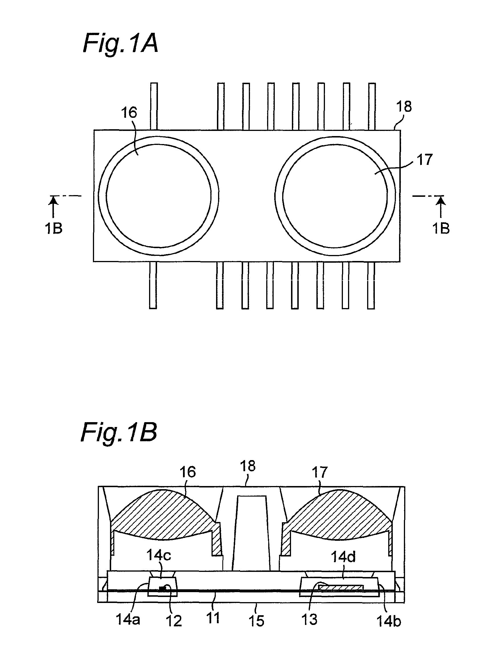
[0062]Hereinbelow, the invention will be described in detail with reference to embodiments shown in the drawings. FIGS. 1A and 1B are diagrams showing a schematic configuration of an optical ranging sensor in accordance with the embodiment. FIG. 1A is a plan view and FIG. 1B is a sectional view taken along a line 1B-1B in FIG. 1A.

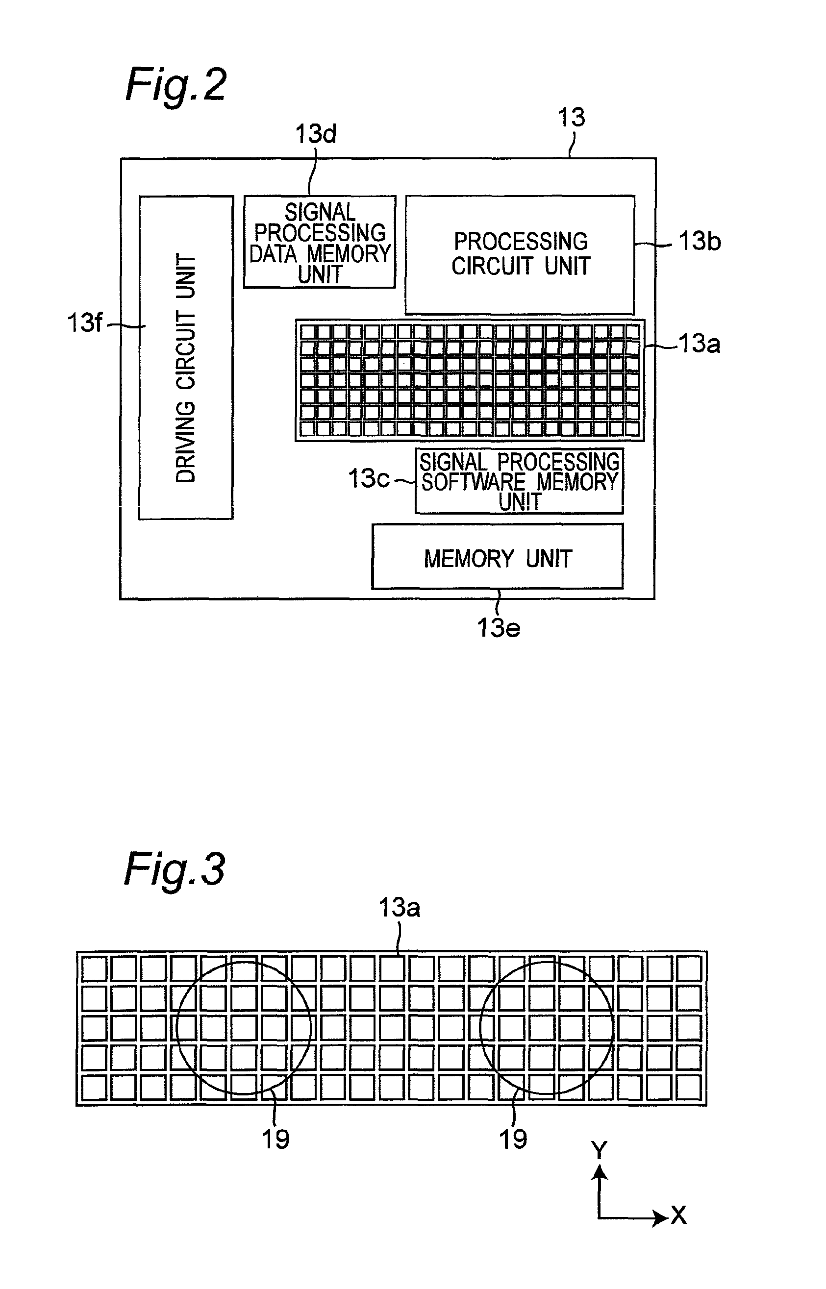
[0063]In the optical ranging sensor, as shown in FIG. 1B, a light emitting element 12 composed of an infrared LED (light emitting diode), an infrared surface emission laser, or the like, and a light receiving element 13 are provided on a lead frame 11. As shown in FIG. 2, the light receiving element 13 includes a position detecting light receiving unit 13a composed of a CMOS area sensor, a CCD (charge coupled device) area sensor, or a photodiode array, of m rows and n columns (m≧2, n≧2), a processing circuit unit 13b for processing signals outputted from the position detecting light receiving unit 13a, a signal processing software memory unit 13c for storin...


PUM


Abstract

An optical ranging sensor includes a light emitting unit for projecting a light beam on an object to be measured, a light receiving unit on which a light spot of reflected light of the light beam from the object is formed, and a processing circuit unit for processing output signals from the light receiving unit and detecting a distance to the object. The light receiving unit includes an effective light receiving part having light receiving cells arranged in matrix form in a first direction in which a position of the light spot moves as the object moves along a direction of an optical axis of the light emitting unit, and in a second direction orthogonal to the first direction. A size of the effective light receiving part in the second direction is not smaller than a radius of the light spot but not larger than a diameter thereof.

Description

BACKGROUND OF THE INVENTION[0001]1. Field of the Invention[0002]The present invention relates to an optical ranging sensor for detecting a distance to an object and also relates to electronic equipment having the optical ranging sensor installed therein.[0003]2. Description of the Related Art[0004]As optical ranging sensors for detecting a distance to an object, conventionally, there have been an optical displacement measuring device (JP 2002-195807 A: Patent Literature 1) and an optical displacement gauge (JP 2006-38571 A: Patent Literature 2) in which light radiated from a light emitting element such as a laser diode is condensed by a light projecting lens, and a resultant beam is projected on an object to be measured, and then a portion of diffuse reflectance light, reflected by a surface of the object to be measured, is condensed by a light receiving lens so as to form a received light spot on a light receiving surface of an MOS (metal oxide semiconductor) image sensor, and fina...

Claims


Application Information

Patent Timeline
Patent Type & Authority Patents(United States)
IPC IPC(8): G01C3/08
CPCG01C3/085
Inventor YAMAGUCHI, AKIFUMIWADA, HIDEOKUBO, MASARULU, JASON CHIH-HUNG
Owner SHARP KK
Why Eureka
Try Eureka