Hand crimp tool

a technology of crimping tool and hand, which is applied in the direction of connection, line/current collector details, electrical apparatus, etc., can solve the problem of no longer being able to operate the lever handle in the closed configuration, and achieve the effect of reducing the need for maintenan

Active Publication Date: 2017-10-10
APTIV TECH LTD
View PDF18 Cites 0 Cited by
  • Summary
  • Abstract
  • Description
  • Claims
  • Application Information

AI Technical Summary

Benefits of technology

[0016]The crimping dies may correspond to crimping dies as they are used in crimping machines for mass production facilities. In other words the dimensions of the crimping dies correspond to the dimensions of those typically used in mass production crimping machines. This offers the possibility to test crimping dies designed for mass production machines by using the hand crimp tool, thereby avoiding the necessity to mount the crimping dies into the mass production crimping machines which might require stopping a whole assembly line.
[0020]Thus, due to the crimping frame, the hand crimp tool requires less maintenance as compared to lever-pivot based crimping tools while, at the same time, it is of a stable and compact construction.
[0022]Thereby, due to the guidance of the carrier within the frame, the orientation of the frame and the direction of movement is secured even throughout many crimping cycles. In other words, due to the inventive crimping frame, the inventive hand crimp tool is less susceptible to misalignment, and the need for maintenance is reduced.

Problems solved by technology

However, for example, security mechanisms are not excluded which, if necessary, allow returning the lever handles into the open configuration, even though the crimping action is not fully completed.
This may for example be necessary when elements of the hand crimp tool are unwittingly tilted or misaligned such that a further operation of the lever handles towards the closed configuration is no longer possible.

Method used


Image

  • Hand crimp tool
  • Hand crimp tool
  • Hand crimp tool

Examples


Embodiment Construction

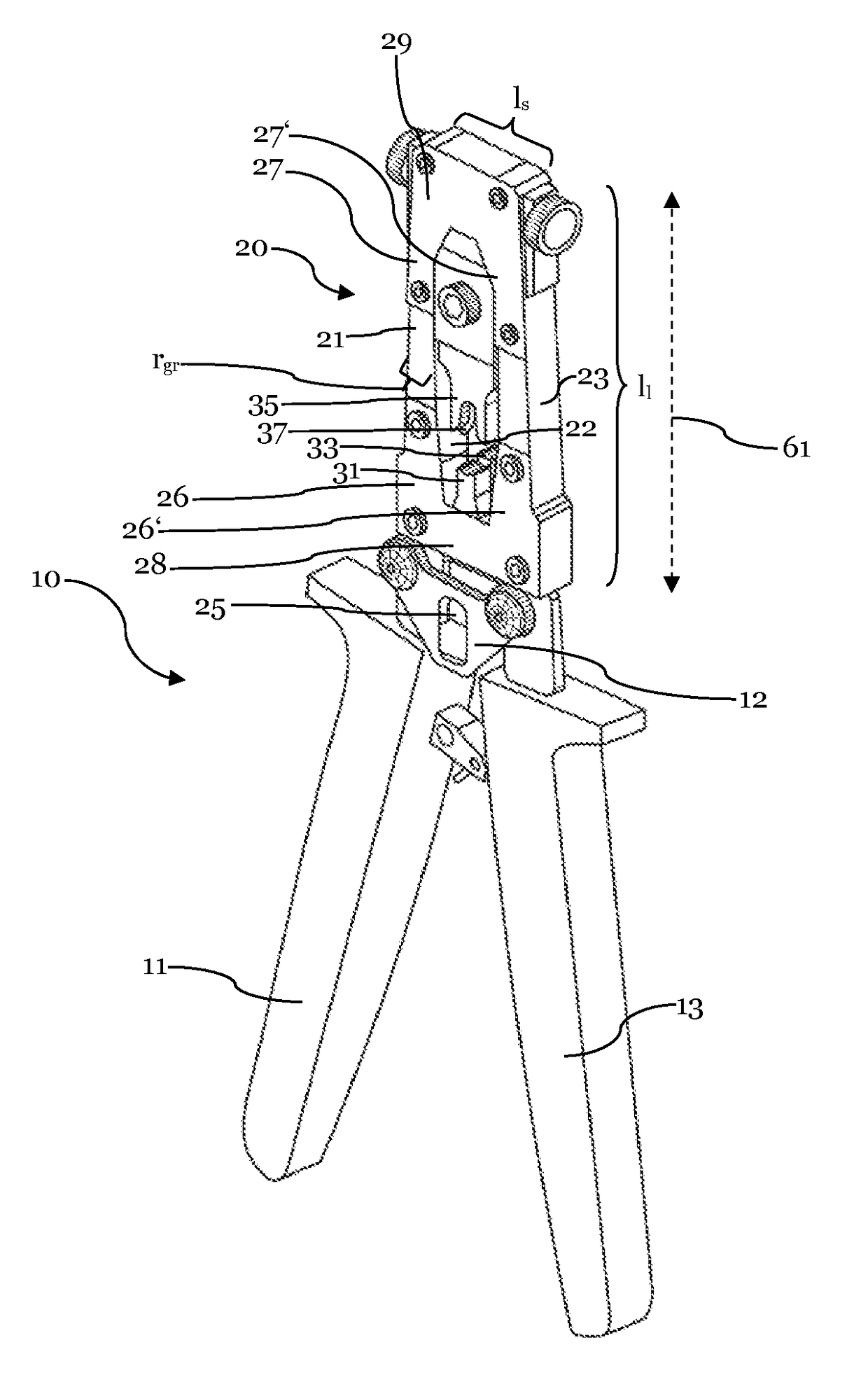
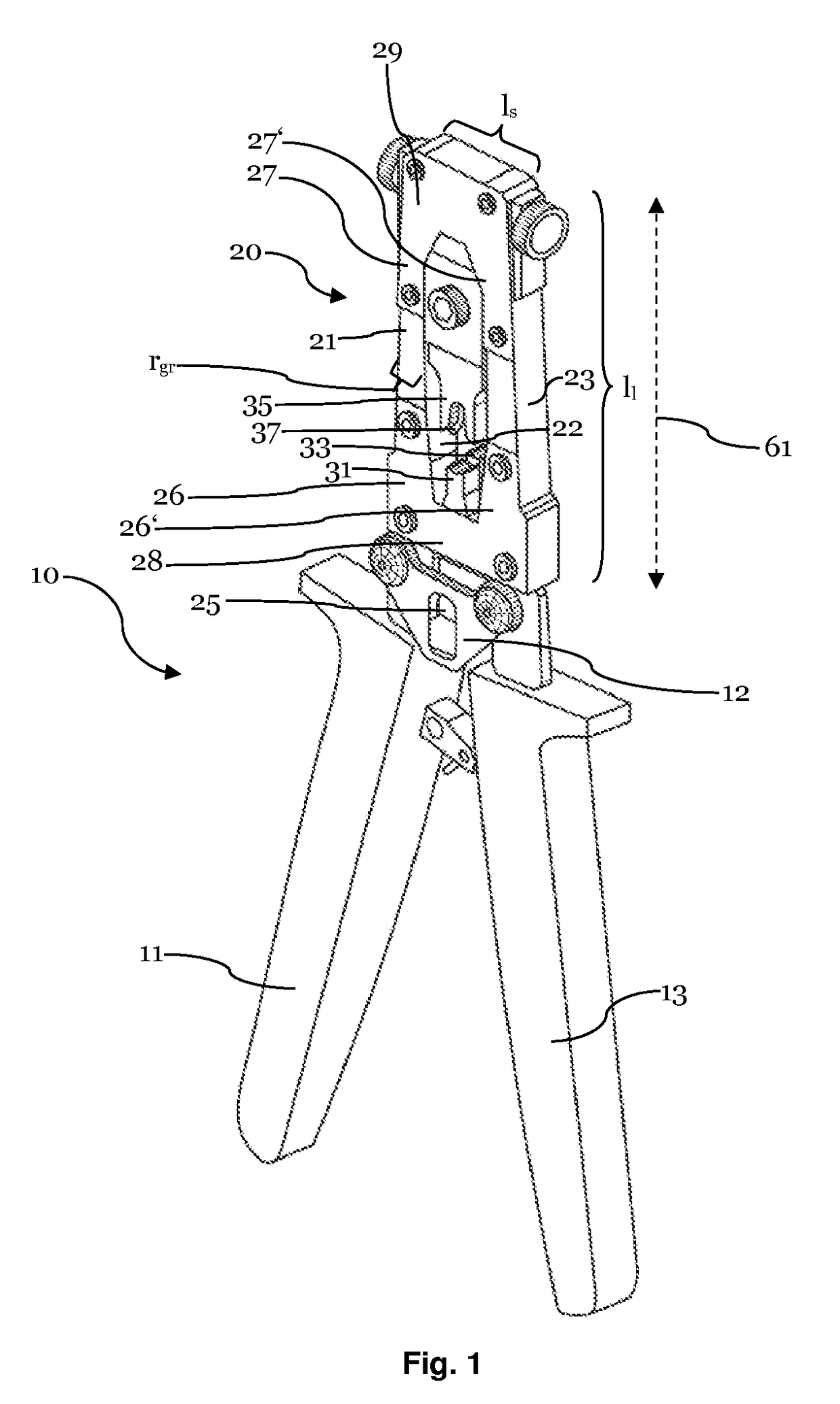
[0028]FIG. 1 shows a hand crimp tool 10 which can be used for crimping contact terminals to electrical cables, wires or similar electrical conductors. As shown, the hand crimp tool 10 comprises first and second lever handles 11, 13 which can be manually operated by a person, for instance pressed together in the shown example, for performing a crimping action.

[0029]In the FIG. 1, the first and second lever handles 11, 13 are shown in an open configuration and upon operation the handles 11, 13 can be brought from the open configuration to a closed configuration.

[0030]As depicted, the hand crimp tool 10 is further provided with a crimping frame 20, which, forms substantially a closed rectangle. Thereby, the closed shape of the crimping frame 20 as it is shown provides for optimal stability of the hand crimp tool 10 and allows a compact construction. Necessary openings, such as an opening for crimping die, can be advantageously incorporated into the compact frame construction.

[0031]As f...


PUM

PropertyMeasurementUnit
lengthaaaaaaaaaa
lengthaaaaaaaaaa
lengthaaaaaaaaaa

Abstract

The invention relates to an hand crimp tool for crimping electrical contact terminals onto electrical cables. This hand crimp tool comprises a crimping frame with two substantially parallel guide rails, and the lever handles configured to be manually operated. The hand crimp tool further comprises a first crimping die and a corresponding second crimping die, at least one of which being mounted to a die carrier. The guide rails are substantially bar-shaped and oriented in a common longitudinal direction. The die carrier is configured to slide in a linear direction parallel to the longitudinal direction of the guide rails, along inner opposite faces of the guide rails, thereby being guided from a cable receiving position to a crimping position.

Description

CROSS-REFERENCE TO RELATED APPLICATION[0001]This application is a national stage application under 35 U.S.C. §371 of PCT Application Number PCT / EP2013 / 063561 having an international filing date of Jun. 27, 2013, which designated the United States, said PCT application claiming the benefit of PCT Application Number PCT / IB2012 / 001664, having an international filing date of Jul. 23, 2013, which also designated the United States, the entire disclosure of each of which are hereby incorporated herein by reference.TECHNICAL FIELD OF THE INVENTION[0002]The present invention relates to a hand crimp tool with removable crimping dies to be used for manually crimping electrical contact terminals onto electrical cables.BACKGROUND OF THE INVENTION[0003]Electrical contact terminals are used for the connection of electrical cables, which typically consist of an insulation sheath surrounding a single conductor or a plurality of wires, to electrical components. In particular in the automotive industr...

Claims


Application Information

Patent Timeline
Patent Type & Authority Patents(United States)
IPC IPC(8): H01R43/042
CPCH01R43/042Y10T29/53226
Inventor JOSSIFIDIS, ILIAS
Owner APTIV TECH LTD
Why Eureka
Try Eureka