Ultrasonic measurement apparatus, ultrasonic head unit, ultrasonic probe, and ultrasonic imaging apparatus

a technology of ultrasonic head units and measurement apparatuses, applied in the direction of mechanical vibration separation, instruments, applications, etc., can solve the problem of difficult miniaturization of an apparatus equipped with such ics

Active Publication Date: 2017-10-17
SEIKO EPSON CORP
View PDF27 Cites 0 Cited by
  • Summary
  • Abstract
  • Description
  • Claims
  • Application Information

AI Technical Summary

Benefits of technology

[0008]According to an aspect of the invention, a first integrated circuit apparatus is arranged at one end of an ultrasonic transducer element array in a first direction, a second integrated circuit apparatus is arranged at the other end, and a first channel group with respect to which the first integrated circuit apparatus performs at least one of signal transmission and reception and a second channel group with respect to which the second integrated circuit apparatus performs at least one of signal transmission and reception are arranged alternately in the second direction. It thereby becomes possible to miniaturize the apparatus.
[0018]According to this configuration, the first integrated circuit apparatus is able to output a transmission signal to odd-numbered channels, and the second integrated circuit apparatus is able to output a transmission signal to even-numbered channels. The arrangement pitch of the channels is thereby smaller than the arrangement pitch of the transmission circuits, enabling an ultrasonic transducer element array having a smaller element pitch to be realized.
[0020]According to this configuration, rather than mounting integrated circuit apparatuses on a rigid board using a flat package or the like, the integrated circuit apparatuses can be mounted on the ultrasonic transducer device, thus enabling the ultrasonic measurement apparatus to be miniaturized.
[0022]According to this configuration, because the 1st to mth element groups are connected in series, the amplitudes of the reception voltages of the 1st to mth element groups are added together, enabling reception sensitivity to be improved. Also, transmission sound pressure can be increased as a result of the ultrasonic transducer elements included in each element group being connected in parallel. This enables an increase in transmission sound pressure to be achieved together with an improvement in reception sensitivity.
[0024]According to this configuration, because the plurality of ultrasonic transducer elements in each element group are connected in series, the amplitudes of the reception voltages of the plurality of ultrasonic transducer elements are added together, enabling the reception sensitivity to be improved. Also, transmission sound pressure can be increased as a result of the 1st to mth element groups being connected in parallel. This enables an increase in transmission sound pressure to be achieved together with an improvement in reception sensitivity.
[0026]According to this configuration, an ultrasonic transducer element array can be configured by ultrasonic transducer elements that use a piezoelectric layer to vibrate a vibration film which closes an opening. This enables the ultrasonic transducer elements to be driven with a drive signal of a lower voltage compared with the case where bulk piezoelectric elements are used, and an integrated circuit apparatus can be manufactured with a process having a low breakdown voltage, thus enabling the integrated circuit apparatus to be formed compactly.

Problems solved by technology

There is a problem in that ICs having a high breakdown voltage typically take up a large mounting area and the number of ICs increases, thus making it difficult to miniaturize an apparatus equipped with such ICs.

Method used


Image

  • Ultrasonic measurement apparatus, ultrasonic head unit, ultrasonic probe, and ultrasonic imaging apparatus
  • Ultrasonic measurement apparatus, ultrasonic head unit, ultrasonic probe, and ultrasonic imaging apparatus
  • Ultrasonic measurement apparatus, ultrasonic head unit, ultrasonic probe, and ultrasonic imaging apparatus

Examples


Embodiment Construction

[0052]Hereinafter, preferred embodiments of the invention will be described in detail. Note that the embodiments described below are not intended to unduly limit the scope of the invention as defined in the claims, and not all combinations of the features described in the embodiments are essential to means for solving the problems addressed by the invention.

1. Comparative Example of the Present Embodiment

[0053]As described above, since an IC having a high breakdown voltage is needed when bulk ultrasonic transducer elements are used, there is a problem in that device miniaturization is not readily achieved. For example, although there is a demand, with portable ultrasonic imaging apparatuses, to miniaturize the probe and the device body, miniaturization is hindered when ICs having a high breakdown voltage are mounted.

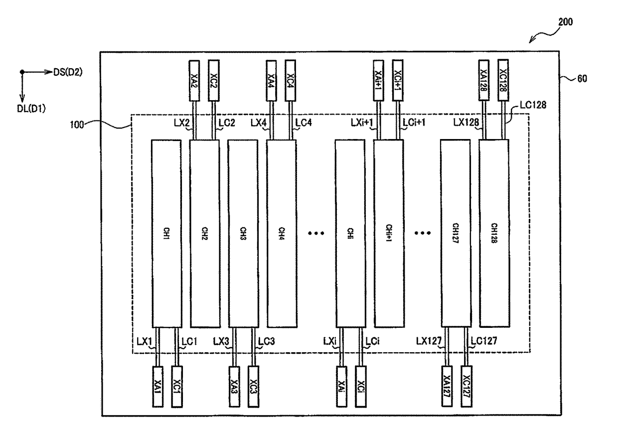
[0054]Also, in JP-A-2005-341085 discussed above, the electrodes of bulk piezoelectric members, which are ultrasonic transducer elements, are connected to a transmission / ...


PUM


Abstract

An ultrasonic measuring apparatus includes an ultrasonic transducer device having a substrate and an ultrasonic transducer element array that has a first channel group and a second channel group that are arranged on the substrate, a first integrated circuit apparatus that is mounted on the substrate, at one edge portion of the ultrasonic transducer element array in a first direction, such that a long-side direction coincides with a second direction that intersects the first direction, and performs at least one of signal transmission to the first channel group and signal reception from the first channel group, and a second integrated circuit apparatus that is mounted on the substrate, at the other edge portion of the ultrasonic transducer element array in the first direction, such that the long-side direction coincides with the second direction, and performs at least one of signal transmission to the second channel group and signal reception from the second channel group. In the ultrasonic transducer element array, the first group of channels and the second group of channels are arranged alternately every channel in the second direction.

Description

BACKGROUND[0001]1. Technical Field[0002]The present invention relates to an ultrasonic measurement apparatus, an ultrasonic head unit, an ultrasonic probe, an ultrasonic imaging apparatus, and the like.[0003]2. Related Art[0004]Heretofore, bulk piezoelectric members have been used as ultrasonic transducer elements that transmit and receive ultrasonic waves. For example, JP-A-2005-341085 discloses an ultrasonic probe in which an insulator layer is provided from a portion of a back surface electrode of a bulk piezoelectric member to a lateral surface of the piezoelectric member, a conductor layer is provided continuously with a front surface electrode of the piezoelectric member so as to wrap around to the back surface electrode side, and wiring formed in a flexible substrate is connected to the conductor layer and the back surface electrode on the back surface side of the piezoelectric member.[0005]A high voltage of around 100 V, for example, is needed in order to drive a bulk piezoe...

Claims


Application Information

Patent Timeline
Patent Type & Authority Patents(United States)
IPC IPC(8): G01S7/56B06B1/06B06B1/02A61B8/00G01S15/89A61B8/13G01S7/52A61B8/08
CPCA61B8/13A61B8/4483B06B1/0215B06B1/0622G01S7/5208G01S7/52085G01S15/8915A61B8/5207A61B8/54B06B2201/51B06B2201/55G01S7/52082A61B8/00G01N29/0654G01N29/07G01S7/52017G01S7/52049G01S7/52053G01S7/52074G01S15/02
Inventor ENDO, KOGO
Owner SEIKO EPSON CORP
Why Eureka
Try Eureka