
Counterweight arm mechanism

a technology of counterweight arm and mechanism, which is applied in the direction of fixed installation, lighting and heating apparatus, and support devices, etc., can solve the problems of high spring stress, subject to a torque, and prone to droop, so as to eliminate or reduce the increased length l, eliminate or improve the deficiency of spring fatigue

Inactive Publication Date: 2017-10-17
HSU CHIA YI
View PDF1 Cites 1 Cited by
  • Summary
  • Abstract
  • Description
  • Claims
  • Application Information

AI Technical Summary

Benefits of technology

This solution enables larger downward folding angles of the lamp arm while reducing the risk of extension spring fatigue by managing tension effectively, allowing the counterweight arm to maintain stability without excessive stress.

Problems solved by technology

When the lamp arm is tilted or stretched, it will be subject to a torque generated by the force of gravity, and will tend to droop.
When the lamp arm of the counterweight arm lamp is folded downward from the horizontal position, the extension spring will be stretched to a great length, causing a high spring stress.
Therefore, the lamp arm of the counterweight arm lamp can not be folded for a large angle, or, due to a large downward folding angle, the extension spring is stretched to its limit, causing fatigue of the extension spring.
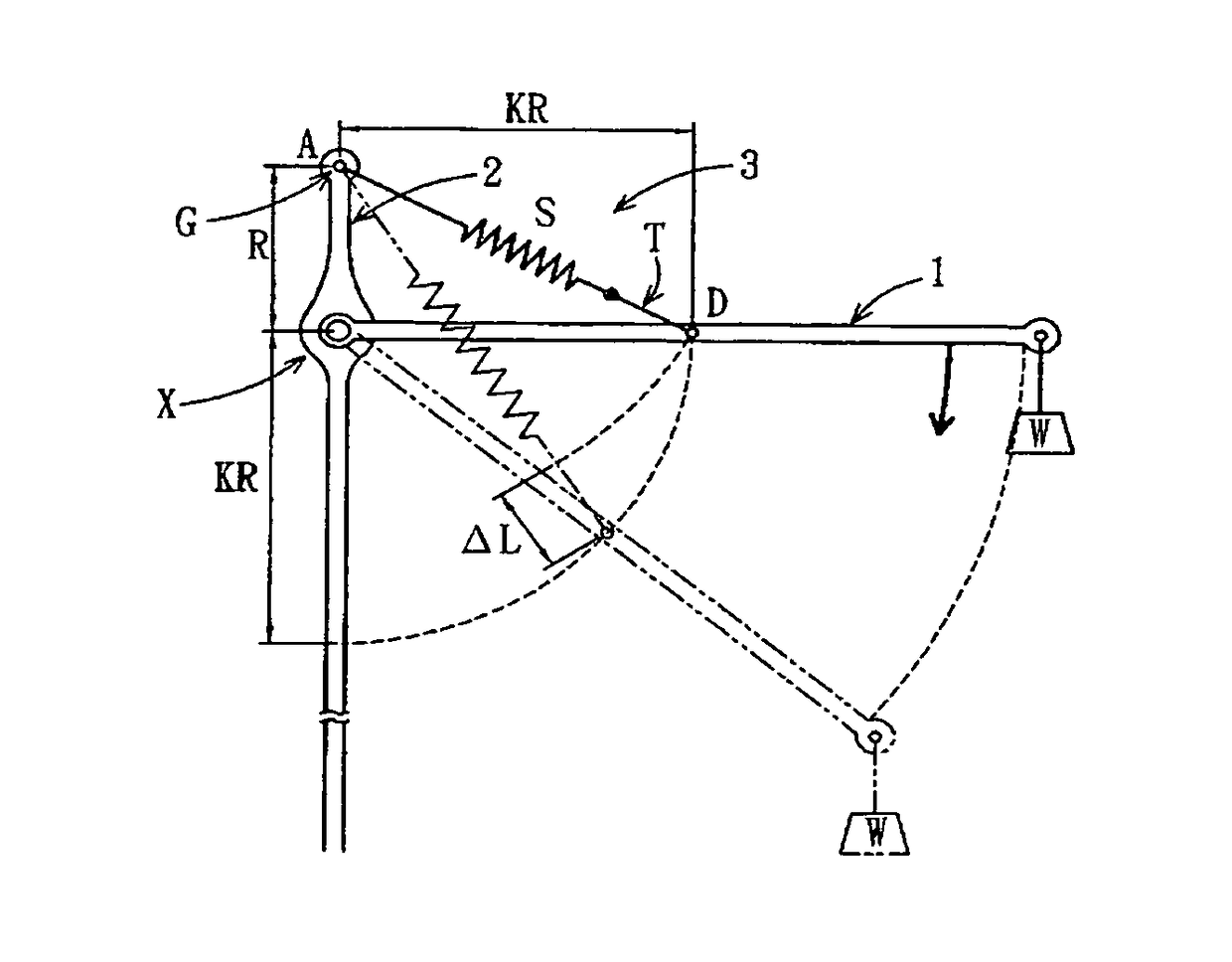
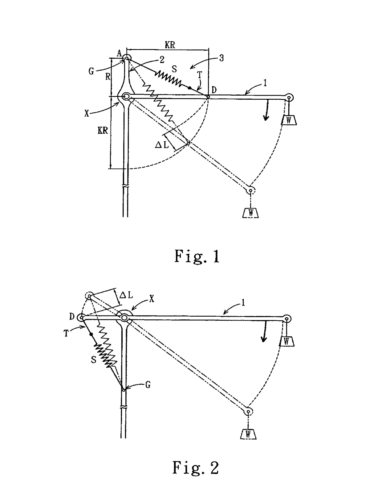
In FIG. 1 and FIG. 2, when the conventional counterweight arm 1 is folded further downward, the extension spring S will be further stretched, but such a stretching is unhelpful.
On the contrary, the conventional counterweight arm 1 has a tendency to be pulled back upward, and as a result, the range of folding the conventional counterweight arm 1 downward is limited; Moreover, the excessive unhelpful stretching of the extension spring S may easily cause fatigue of the extension spring.

Method used


Image

  • Counterweight arm mechanism
  • Counterweight arm mechanism
  • Counterweight arm mechanism

Examples


Embodiment Construction

[0071]With reference to the accompanied drawings, detailed descriptions of the present invention are provided below including structural features, technical solutions, working principles and application examples.

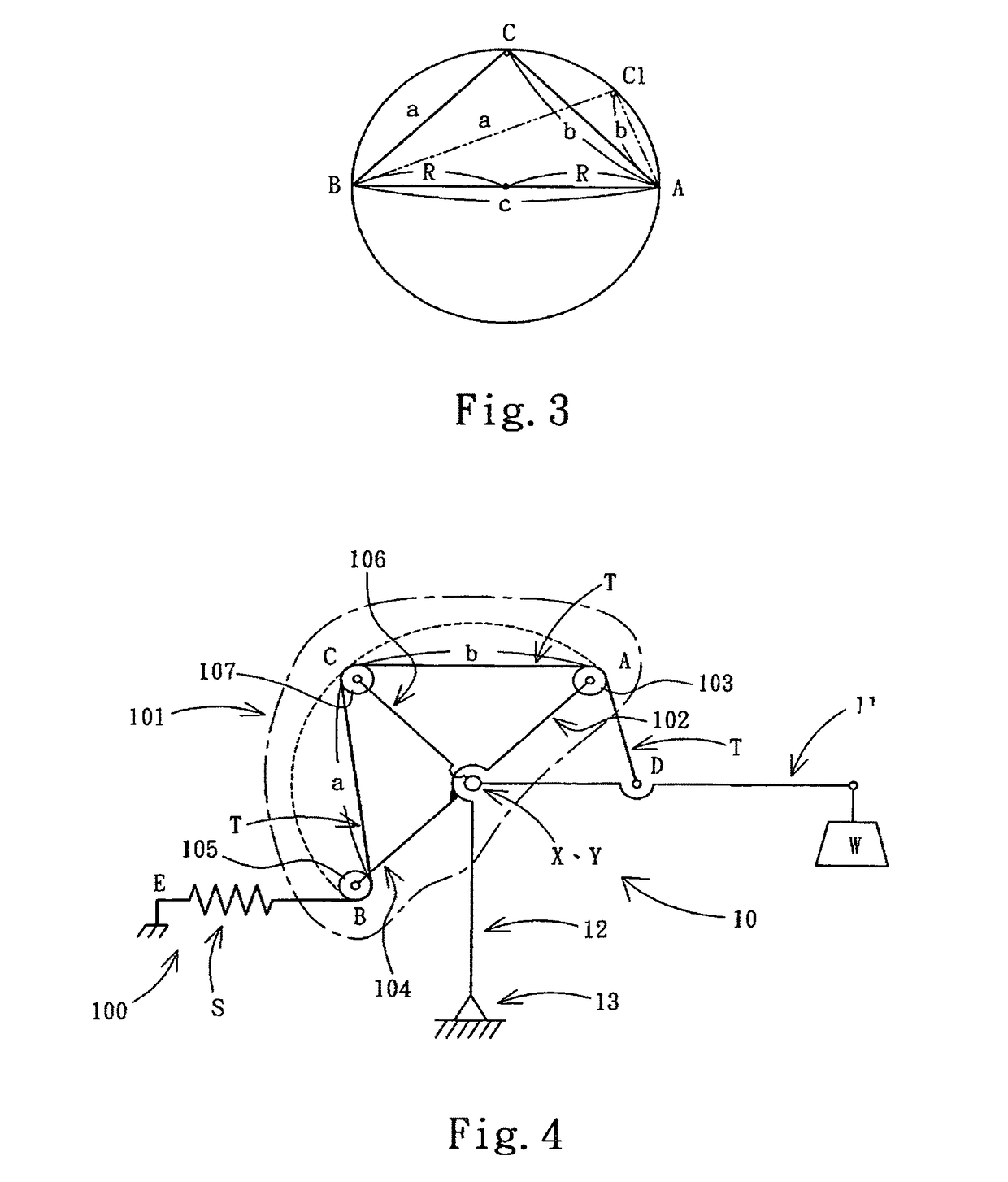
[0072]FIG. 3 is an illustration of the principle of the present invention, wherein, a, b, and c are respectively sides opposite ∠A, ∠B, ∠C ofΔABC. According to the law of sines, a / sin A=b / sin B=c / sin C=2R, where, R is radium of the circumscribed circle of ΔABC.

[0073]When ∠C is a right angle, ΔABC is a right angle triangle, the side opposite ∠C is hypotenuse c, the length of hypotenuse c is 2R, and a and b are catheti.

[0074]When vertex C of ∠C moves along the arc of the circumscribed circle with radium being R, for example, to the position marked by C1, ΔABC will remain as a right angle triangle.

[0075]According to the law of sines, sum of catheti of a right angle triangle ΔABC a+b=2R(sin A+sin B)=2R(sin A+cos A).

[0076]Moreover, according to the feature that any linear combina...


PUM


Abstract

A counterweight arm mechanism having an adjustable dragline tension system capable of adjusting tension; the system comprising a dragline, an extension spring, and a dragline adjustment mechanism; the dragline adjustment mechanism adjusted the overall length of the dragline as a function of the rotation angle of a counterweight arm; the dragline length adjustment mechanism being implemented according to the two legs of a right-angled ΔABC and the property of a+b=2√2R sin(A+π / 4); when the counterweight arm rotates, the mechanical structure can be used to drive the vertex of the right angle of the right-angled ΔABC to rotate along with the counterweight arm, and synchronously move in line with the circumcircle of the right-angled ΔABC, thus the tension on the counterweight arm from the adjustable dragline tension system changes with the rotation angle of the counterweight arm.

Description

BACKGROUND OF INVENTION[0001]1. Field of the Invention[0002]The present invention relates to a counterweight arm mechanism, particularly to a passive counterweight arm mechanism that uses an extension spring to provide tension, and more particularly to a counterweight arm mechanism that can adjust the stretched length of the extension spring to adjust the tension of the tension system. Said tension system refers to a dragline tension system comprising an extension spring and a dragline.[0003]2. Description of Related Art[0004]Counterweight arms are commonly seen mechanical devices with wide applications in, for example, counterweight arm suspenders, medical shadowless lamps, robot arms, counterweight arm lamps etc, wherein, counterweight arm lamps are very common equipment in living and working environments.[0005]A counterweight arm lamp is a lamp with a foldable and extendable lamp arm for diversified lighting needs.[0006]Generally, a counterweight arm lamp has a structure similar ...

Claims


Application Information

Patent Timeline
Patent Type & Authority Patents(United States)
IPC IPC(8): F21S8/08F16M11/20F16M11/10F21V21/14F21S6/00
CPCF21V21/14F16M11/10F16M11/2014F16M11/2021F16M2200/041F21S6/003
Inventor HSU, CHIA-YI
Owner HSU CHIA YI
Learn More