Frequency-Dependent Damping Valve Arrangement

a frequency-dependent damping and valve arrangement technology, applied in the direction of spring/damper functional characteristics, vibration dampers, shock absorbers, etc., can solve the problems of difficult to find a vibration damper that can achieve this compromise, drive up production costs, and reduce the effect of damping

Inactive Publication Date: 2018-07-05
ZF FRIEDRICHSHAFEN AG
View PDF0 Cites 4 Cited by
  • Summary
  • Abstract
  • Description
  • Claims
  • Application Information

AI Technical Summary

Benefits of technology

[0016]To empty the control chamber faster and, accordingly, to return the control piston in the control pot of the control arrangement faster, it can be quite advantageous when the outlet connection comprises an outlet restrictor formed at the control pot and / or at the control piston.
[0017]Investigations have shown that it is particularly advantageous when the smallest cross-sectional area of the inlet connection has an extension of between 0.1 mm2 and 4 mm2 and when the smallest cross-sectional area of the outlet connection has an extension of between 0 mm2 and 8 mm2.

Problems solved by technology

It is very difficult to find this compromise in a vibration damper with a conventional, non-electronic damping valve arrangement that is adjustable by an actuator.
However, the smaller amplitudes at middle and higher frequencies which have a similar speed level are also highly attenuated in these vibration dampers, which leads to loss of comfort.
However, all known damping valve arrangements stand out as highly complicated, which drives up production costs and requires a very highly precise adjustment.

Method used


Image

  • Frequency-Dependent Damping Valve Arrangement
  • Frequency-Dependent Damping Valve Arrangement
  • Frequency-Dependent Damping Valve Arrangement

Examples


Embodiment Construction

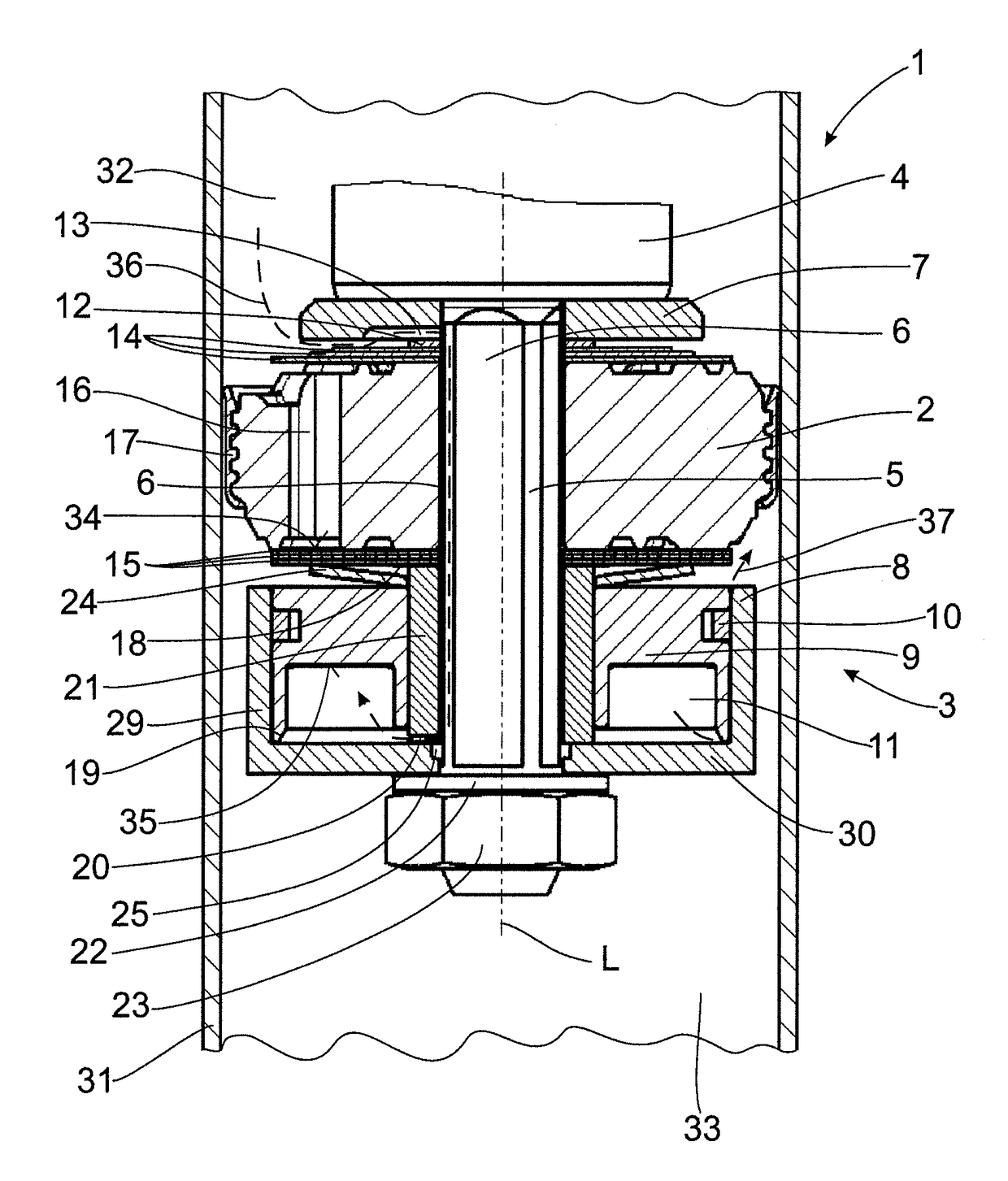
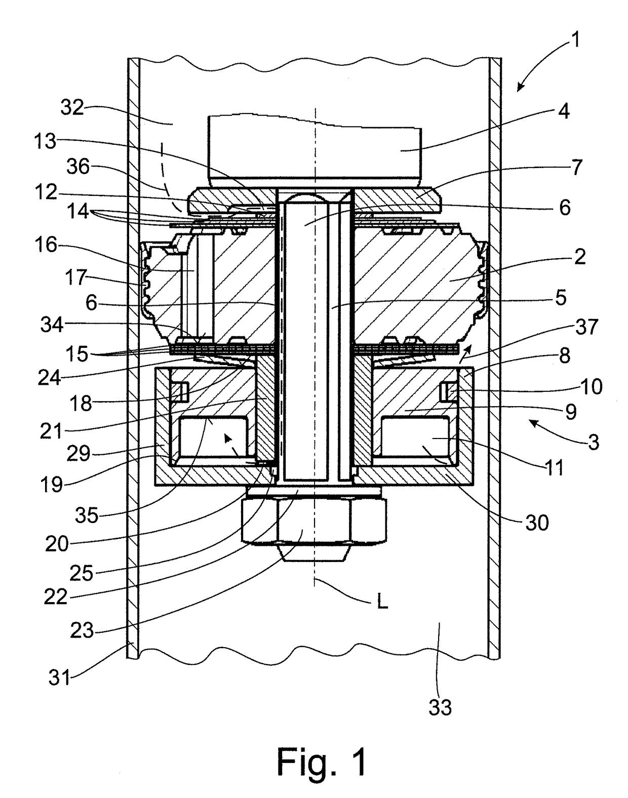
[0021]FIG. 1 shows an exemplary construction variant of a damping valve arrangement with a frequency-dependent damping force characteristic.

[0022]FIG. 1 shows a piston rod 4, which has a piston rod tenon 5, as it is called. The piston rod tenon 5 is a portion of the piston rod 4 having a reduced diameter. The damping valve arrangement 1 in its entirety is threaded onto the piston rod tenon 5 and is axially clamped between a portion of the piston rod 4, which portion adjoins the piston rod tenon 5 and has a larger diameter than the piston rod 5, and fastener 23 shown in FIG. 1 as a piston rod nut.

[0023]As is shown in FIG. 1, the damping valve arrangement 1 comprises a damping piston 2 arranged inside a cylinder 31 filled with a damping fluid and which is axially secured to a piston rod 4. The damping piston 2 is outfitted with a piston seal 17 which radially seals it relative to the cylinder 31. The damping piston 2 which is fixed to the piston rod 4, is arranged to be axially displa...


PUM


Abstract

A damping valve arrangement for a vibration damper includes a damping piston with a check valve and a control arrangement with a control piston. A spring element is arranged between the control piston and the check valve that loads a valve disk axially in direction of a flow channel and the control piston in direction of the pot base 30 with a defined spring force. A surface of the control piston facing the control space is greater than a surface of the valve disk bounded by the flow channel. A smallest cross-sectional area Az of the inlet connection opening into the control space and a smallest cross-sectional area Aa of the outlet connection leading out of the control space are dimensioned such that their ratio to one another is between 0.2 and 5 according to the condition Az/√{square root over (Aa)}.

Description

CROSS REFERENCE TO RELATED APPLICATIONS[0001]This is a U.S. national stage of application No. PCT / EP2015 / 059017, filed on Apr. 27, 2015. Priority is claimed on German Application No. DE102014210705.9, filed Jun. 5, 2014, the content of which is / are incorporated here by reference.BACKGROUND OF THE INVENTION1. Field of the Invention[0002]The invention is directed to a damping valve arrangement with a frequency-dependent damping force characteristic.2. Description of Prior Art[0003]A vibration damper in a motor vehicle is provided to damp vibrations excited by the uneven road surface. In doing so, there must always be a compromise between driving safety and driving comfort. A vibration damper with a stiff damping valve arrangement having a high damping force characteristic is optimal for high driving safety. If greater comfort is demanded, the damping valve arrangement should be adjusted to be as soft as possible. It is very difficult to find this compromise in a vibration damper with ...

Claims


Application Information

Patent Timeline
Patent Type & Authority Applications(United States)
IPC IPC(8): F16F9/348F16F9/512
CPCF16F9/3488F16F9/5126F16F2228/066F16F2228/08
Inventor FORSTER, ANDREASSIEBER, ANDREAS
Owner ZF FRIEDRICHSHAFEN AG
Why Eureka
Try Eureka