Storage system for storing laboratory objects at low temperatures

a laboratory object and storage system technology, applied in the field of storage arrangement, can solve the problems of difficult automation and low temperature storage of laboratory objects, and achieve the effect of improving space utilization

Active Publication Date: 2012-05-31
LICONIC
View PDF11 Cites 46 Cited by
  • Summary
  • Abstract
  • Description
  • Claims
  • Application Information

AI Technical Summary

Benefits of technology

[0023]Advantageously, a rotatable carousel is provided in each Dewar flask on which carousel the storage cassettes are arranged. Each storage cassette can thereby be brought into the active area of the picking device. Furthermore, a carousel is particularly suitable for installation in the normally round Dewar flasks. To improve the utilization of space, the storage cassettes are advantageously arranged in several concentric circles around a rotational axis of the carousel.
[0024]The picking device can also have a sample removal device, with which an individual laboratory object can be removed from a sample plate removed from a storage cassette or inserted into the sample plate. In this manner in the case of a sample plate which holds several laboratory objects, only one can be removed. The paths are thereby shorter and the other laboratory objects can be quickly returned to the Dewar flask.

Problems solved by technology

The storage of laboratory objects at very low temperatures, such as temperatures below 160° C., for example, typically at −196° C., is very complex and automation is difficult to achieve.
A storage arrangement for low temperatures is known from EP 1 972 874, but this system is suitable for really low temperatures only to a limited extent.

Method used


Image

  • Storage system for storing laboratory objects at low temperatures
  • Storage system for storing laboratory objects at low temperatures
  • Storage system for storing laboratory objects at low temperatures

Examples


first embodiment

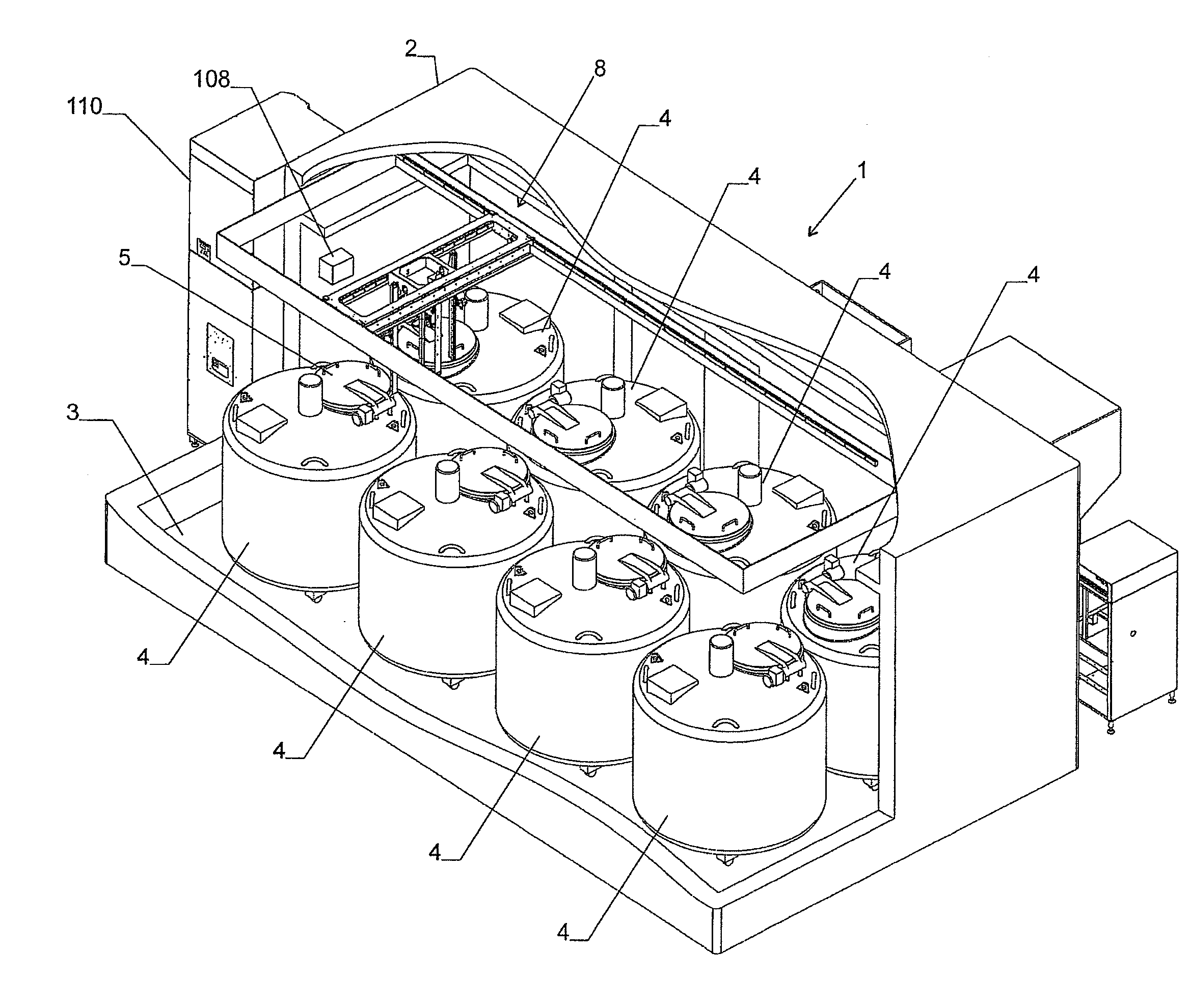
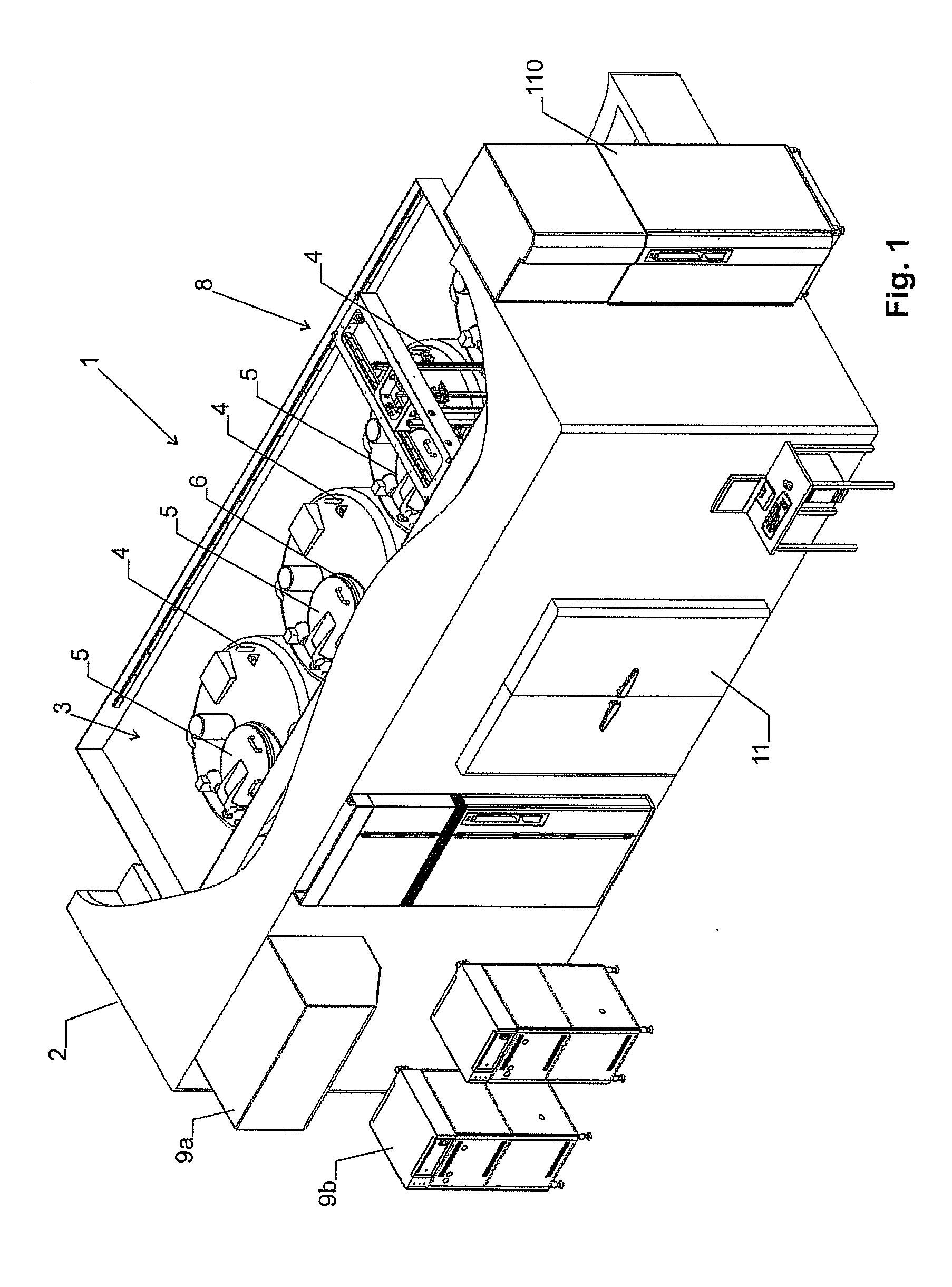
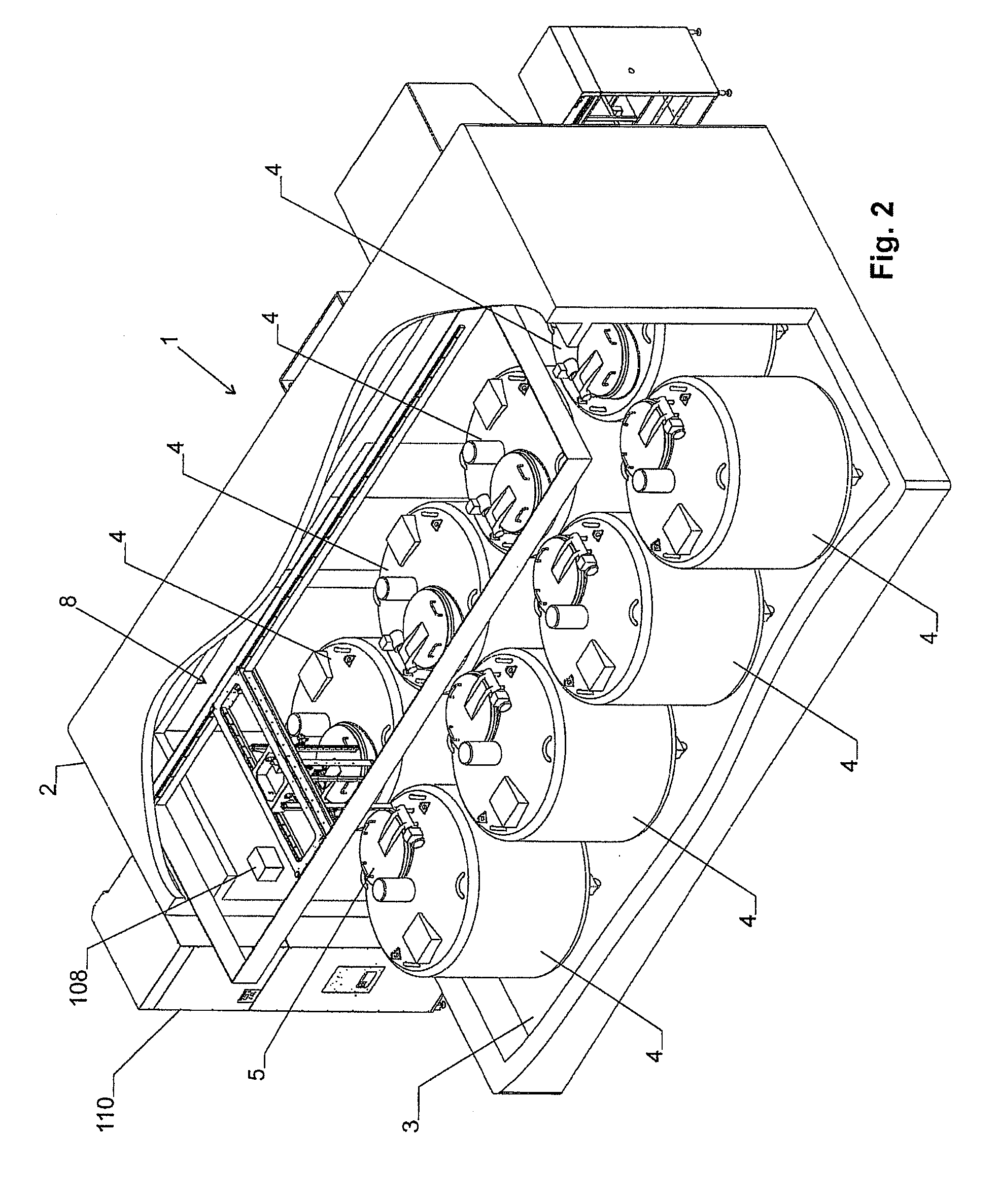
[0057]a Dewar flask 4 is shown in FIGS. 3-5. It has an essentially cylindrical housing 10, in which the above-mentioned vacuum insulation 12 is attached. The vacuum insulation 12 surrounds an inner space 14, which accommodates a carousel 18 that can be rotated about a vertical rotational axis 16. The carousel 18 bears on a base plate 19 a plurality of storage cassettes 20.

[0058]A positioning drive 22 is used to rotate the carousel 18 around the rotational axis 16 and to bring it into defined positions.

[0059]The storage cassettes 20 are arranged in several concentric circles around the rotational axis 16, positioned radially by means of vertical walls 24 and are moveable in the vertical direction.

[0060]The lid 5 can be automatically opened and closed with a door drive 26. It is arranged on the top of the Dewar flask 4 and positioned and dimensioned such that when the lid 5 is opened, each storage cassette 20, which has been rotated with the positioning drive 22 into the region of the...

second embodiment

[0061]a Dewar flask is shown in FIG. 20. In particular the double wall with the vacuum insulation 12 as well as the opening 6 closed by the lid 5 (not shown) can be seen in FIG. 20. In turn a carousel 18 is located in the interior of the Dewar flask, which carousel bears on its base plate 19 a plurality of storage cassettes (not shown).

[0062]In the embodiment according to FIG. 6, a centering element 95 is arranged in the opening 6, the function of which centering element is explained below.

Storage Cassettes:

[0063]FIGS. 6-8 show an advantageous storage cassette 20. It has two parallel, vertical side walls 30 and perpendicular thereto a vertical back wall 32. The storage cassette is open opposite the back wall 32 so that access to the sample plates accommodated in the storage cassette is possible. A top part 34 is arranged at the upper end of the storage cassette 20, to which top part the side walls 30 and the back wall 32 as well as a handle 36 projecting upwards are attached. The ha...

third embodiment

[0090]FIGS. 15-18 show a cassette lift 60. It corresponds structurally to that according to FIGS. 12-14, with the differences described below.

[0091]The third embodiment of the cassette lift is not based on a telescopic arrangement of elements. Instead, the chain 80 together with rollers 96, 97 forms a pulley which is used to lower the gripper device 88 into the Dewar flasks 4. To this end, the chain is deflected over at least one lower and at least one upper roller 96 and 97 respectively, cf. FIG. 18. One of the rollers, advantageously the lower roller 96, can be displaced in the vertical direction via the vertical drive 66, while the other roller and the upper end of the chain 80 are vertically stationary.

[0092]In the embodiment shown, the vertical drive is arranged on the first vertical rail 69 of a rail carrier 62 (FIG. 18). The rail carrier 62 corresponds to the first telescopic element 62 of the previous embodiments and is fixedly arranged on the carriage 56.

[0093]The chain 80 ...


PUM


Abstract

The storage arrangement has a chamber. Several Dewar flasks are arranged in the chamber and above them a picking device. The picking device has at least one cassette lift, with which storage cassettes can be removed from above from the Dewar flasks. This arrangement is suitable for storing laboratory objects at very low temperatures.

Description

CROSS-REFERENCE TO RELATED APPLICATIONS[0001]The present application claims priority under 35 U.S.C. §119 of / Swiss Patent Application No. CH-1968 / 10, filed on Nov. 24, 2010, the disclosure of which is expressly incorporated by reference herein in its entiretyBACKGROUND OF THE INVENTION[0002]1. Field of the Invention[0003]The invention relates to a storage arrangement for storing laboratory objects at very low temperatures.[0004]2. Discussion of Background Information[0005]The storage of laboratory objects at very low temperatures, such as temperatures below 160° C., for example, typically at −196° C., is very complex and automation is difficult to achieve. A storage arrangement for low temperatures is known from EP 1 972 874, but this system is suitable for really low temperatures only to a limited extent.SUMMARY OF THE INVENTION[0006]The object is therefore to provide a storage arrangement of the type mentioned at the outset, which can be operated automatically.[0007]This object i...

Claims


Application Information

Patent Timeline
Patent Type & Authority Applications(United States)
IPC IPC(8): B01L3/00
CPCF25D3/10F25D25/005G01N35/0099F25D13/06G01N2035/0425G01N2035/00445F25D13/04G01N35/028
Inventor MALIN, COSMAS G.
Owner LICONIC
Why Eureka
Try Eureka