Hydrotreating device and application thereof as well as residual oil hydrotreating method

A technology for hydrotreating and residual oil hydrogenation, which is applied in hydrotreating process, hydrocarbon oil treatment, petroleum industry, etc., can solve the problem of wasting reactor space, etc., and achieves the advantages of less risk, simple switching procedure and less high-pressure valves. Effect

Active Publication Date: 2013-04-24
CHINA PETROLEUM & CHEM CORP +1
View PDF6 Cites 61 Cited by
  • Summary
  • Abstract
  • Description
  • Claims
  • Application Information

AI Technical Summary

Problems solved by technology

However, this method always has a protective reactor offline, and the utilization efficiency of the protective reactor is only 50%, wasting precious reactor space

Method used


Image

  • Hydrotreating device and application thereof as well as residual oil hydrotreating method
  • Hydrotreating device and application thereof as well as residual oil hydrotreating method

Examples


Embodiment 1

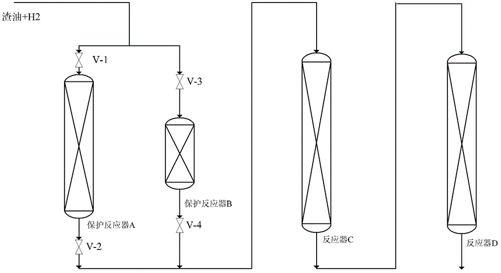
[0038] 60ml of hydrogenation protection catalyst RG-10B and 60ml of hydrogenation demetallization catalyst RDM-2B are sequentially filled in protection reactor A, and 30ml of hydrogenation protection catalyst RG-10B and 10ml of hydrogenation demetallation catalyst RDM-2B are sequentially filled in protection reactor B 2B, 200ml of hydrodemetallization catalyst RDM-2B is filled in reactor C, and 400ml of hydrodesulfurization catalyst RMS-1B is filled in reactor D.

[0039] The raw material residue M1 (see Table 1 for the composition) is mixed with hydrogen and enters the protection reactor A, and then enters the reactor C and the reactor D. The operating conditions include: the residual oil feed rate is 180g / h, the hydrogen flow rate at the reactor inlet is 126L / h, the pressure is 15.0MPa, the reaction temperature is adjusted in the range of 350-410°C according to the sulfur content of the hydrogenated oil, so The sulfur content of the hydrotreated oil was maintained at 0.30% b...

Embodiment 2

[0052] Fill protection reactor A with 40ml protection agent RG-10B and 100ml demetallization catalyst RDM-2B in turn, protection reactor B with 20ml protection agent RG-10B and 20ml demetallation catalyst RDM-2B, and reactor C with 300ml Demetallization catalyst RDM-2B, reactor D is filled with 300ml desulfurization catalyst RMS-1B.

[0053]The raw material residue M2 (the composition is shown in Table 1) is mixed with hydrogen and enters the protection reactor A, and then enters the reactor C and the reactor D. A sampling point is set after the protection reactor and before the reactor C to monitor the demetallization performance of the protection reactor. The operating conditions include: feed rate of residue oil is 140g / h, hydrogen flow rate at reactor inlet is 98L / h, pressure is 14.5MPa, reaction temperature of protection reactor A is based on the residue oil collected at the sampling point after protection reactor A The metal (Ni+V) content in the reactor is adjusted wit...


PUM

PropertyMeasurementUnit
volume ratioaaaaaaaaaa

Abstract

The invention provides a hydrotreating device which comprises a hydrotreating protection unit and a main hydrotreating unit, which are connected with each other in series, wherein the hydrotreating protection unit comprises a main hydrotreating protection reactor and a spare hydrotreating protection reactor, which are connected with each other in parallel, and the volume of the main hydrotreating protection reactor is larger than that of the spare hydrotreating protection reactor. The invention further provides the application of the hydrotreating device and a residual oil hydrotreating method. The method comprises the following steps of: introducing the residual oil and the hydrogen into the hydrotreating device, and alternately using the main hydrotreating protection reactor and the spare hydrotreating protection reactor in the process of hydrotreating, wherein the online time of the main hydrotreating protection reactor is longer than that of the spare hydrotreating protection reactor. The method provided by the invention is particularly suitable for machining the high-carbon content residual oil and the high-metal content residual oil. Furthermore, the bigger hydrotreating protection reactor is longer in online time, so that the invention is higher in reactor use ratio.

Description

technical field [0001] The invention relates to a hydrotreating device, the application of the hydrotreating device and a residual oil hydrotreating method utilizing the hydrotreating device. Background technique [0002] Residue hydrogenation unit has become an important technology for clean processing of high-sulfur and high-metal residues in refineries because of its high liquid product yield and environmental friendliness. At present, there are four main types of residual oil hydrotreating processes in the world, namely fixed bed, ebullated bed, moving bed and suspended bed. Among them, the fixed bed process is the most widely used process in residual oil hydrogenation due to its high desulfurization efficiency, better operation safety and mature technology than other hydrogenation processes. However, for the fixed-bed residual oil hydrogenation process, metal impurities (such as vanadium, nickel, calcium, iron, etc.), unsaturated components and scales in the residual o...

Claims


Application Information

Patent Timeline
Patent Type & Authority Applications(China)
IPC IPC(8): C10G65/02
Inventor 牛传峰戴立顺邵志才刘涛董凯聂红杨清河胡大为孙淑玲
Owner CHINA PETROLEUM & CHEM CORP
Why Eureka
Try Eureka