Electromagnetic Fuel Injection Valve Device

a fuel injection valve and electromagnetic technology, applied in the direction of electrical control, process and machine control, instruments, etc., can solve the problem of lower severity, and achieve the effect of reducing the motion of the movable core and reducing the time from the completion of the injection to the start of the next injection

Inactive Publication Date: 2008-11-13
HITACHI LTD
View PDF9 Cites 50 Cited by
  • Summary
  • Abstract
  • Description
  • Claims
  • Application Information

AI Technical Summary

Benefits of technology

[0013]This makes it possible to suppress the motion of the movable core after the valve element is brought into contact with the valve seat, and to quickly return the movable core to the initial position where it was at the start of valve opening operation.
[0014]According to the invention, the movable core can be quickly returned to the initial position where it was at the start of valve opening operation. Therefore, it is possible to provide a fuel injection valve wherein the time from the completion of injection to the start of the next injection is shortened.

Problems solved by technology

This problem, though its severity is lower, also arises in constructions in which the movable core and the valve element are joined to each other.

Method used


Image

  • Electromagnetic Fuel Injection Valve Device
  • Electromagnetic Fuel Injection Valve Device
  • Electromagnetic Fuel Injection Valve Device

Examples


first embodiment

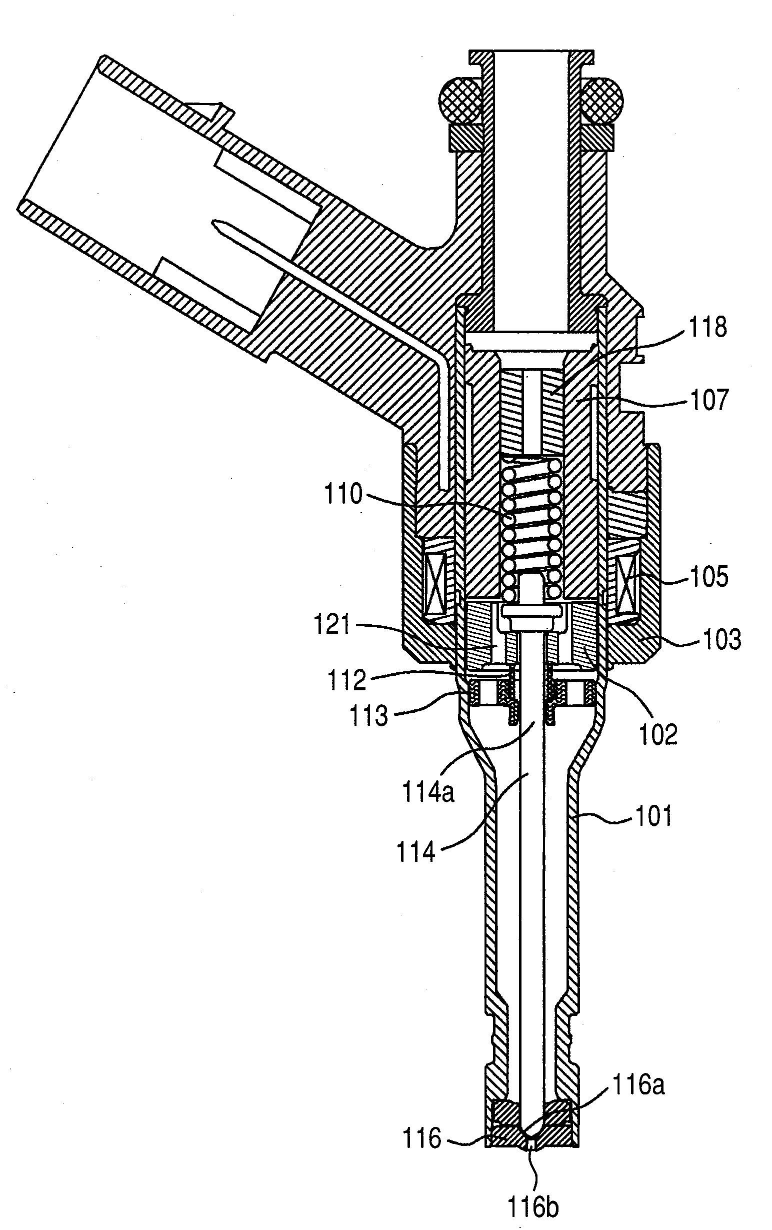
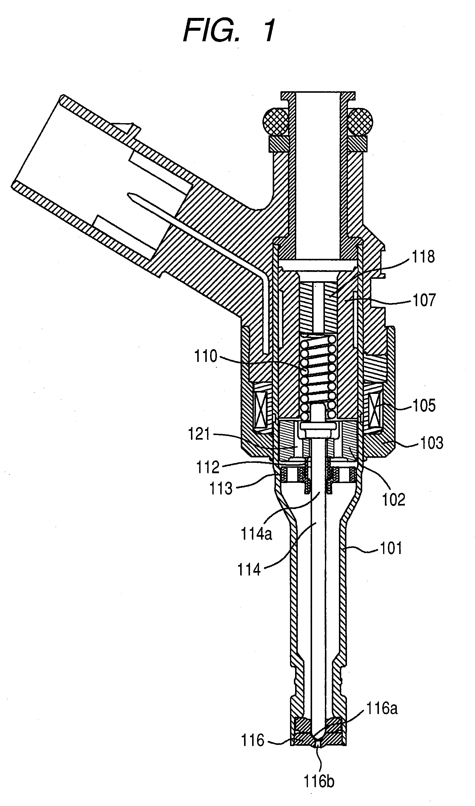
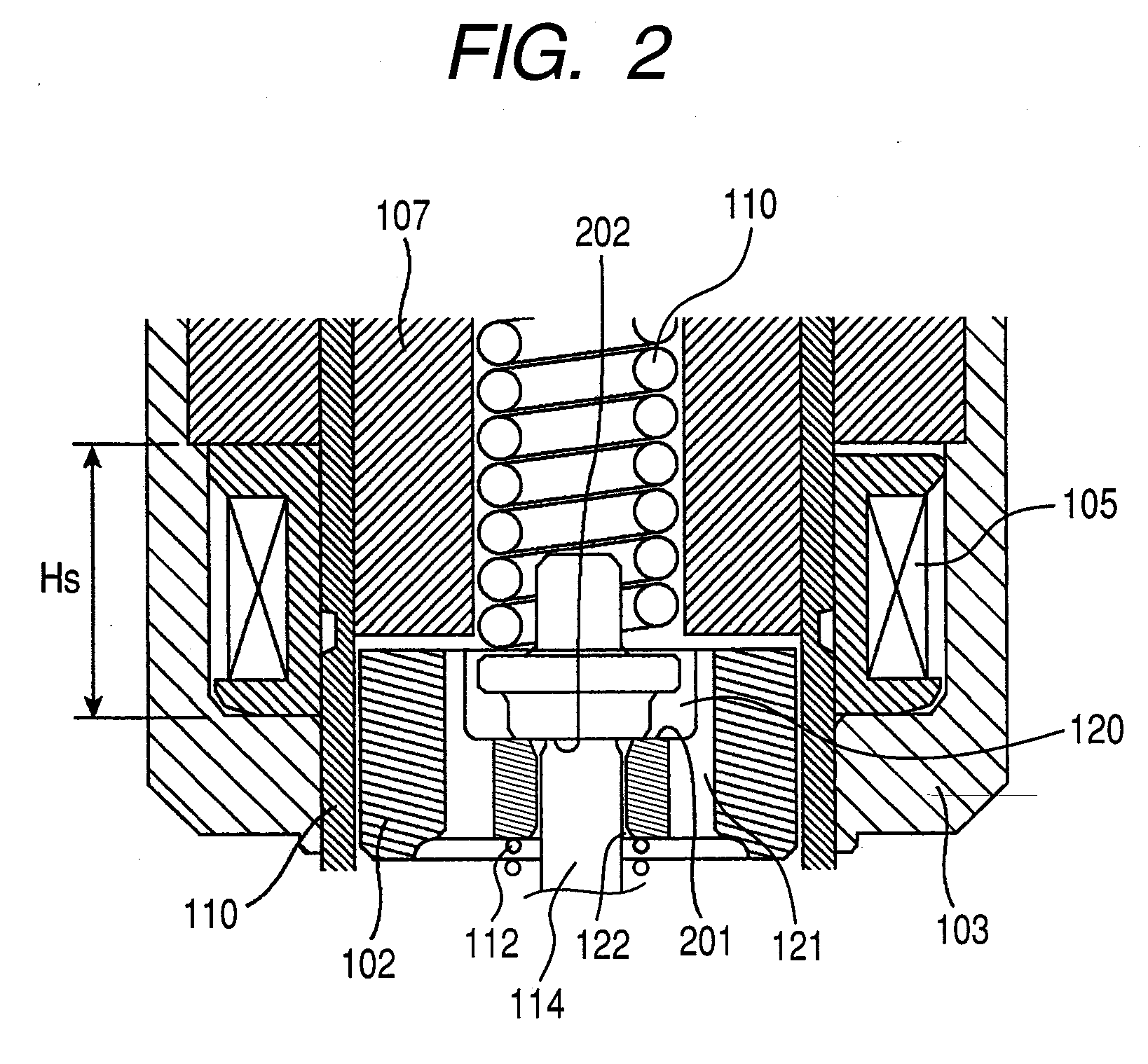
[0024]FIG. 1 is a sectional view of a fuel injection valve of the present invention, and FIG. 2 is an enlarge view of an area in proximity to a movable core.

[0025]The fuel injection valve illustrated in FIG. 1 is a normally closed type electromagnetic valve (electromagnetic fuel injection valve).

[0026]In the fuel injection valve of the embodiment, a movable core 102, a stationary core 107, a return spring 110, a movable core-initial positioning spring 112, a valve rod guide 113, a needle type valve element 114, a nozzle member 116 with a valve seat 16a and a nozzle orifice 116b, and a cylindrical-shape spring retainer 118 etc. are incorporated inside of a cylindrical valve housing 101. The spring retainer 118 is fixed inside of the stationary core 107, and the return spring 10 is interposed between the spring retainer 118 and a valve rod 114a in the stationary core 107. The valve rod guide 113 having fuel-through holes is fixed an inner wall of the valve housing 101. The valve rod g...

second embodiment

[0046]FIG. 6 is a flowchart illustrating current control (energization control) in a second embodiment of the invention. In this embodiment, the mid-term energization after the valve is closed (namely after the injection control pulse is turned off) is not stopped in a certain time period t5-t6 (refer to FIG. 7), as indicated in Block 601. Namely, as shown in FIG. 7, after a driving current 706 of the mid-term energization reached to a predetermined threshold value 710, the applied current is subsequently continued with an approximately predetermined constant current value (refer to a reference numeral 713). Since it is required to discriminate a normal type fuel injection and a divided type fuel injection from each other, the following measure is taken: in addition to the normal injection control pulse 804, plural time-fuel injection discrimination mode (in one stroke of an internal combustion engine) pulse 807 is inputted from the ECU 803 in FIG. 8 to the driving current control c...


PUM


Abstract

An electromagnetic fuel injection valve device for an internal combustion engine is configured to carry out an energization to an electromagnetic coil of an injection valve actuator for a valve opening motion and additionally carry out a mid-term energization at a time interval between both an energization for valve opening of a previous fuel injection and an energization for valve opening of a subsequent fuel injection. A current of the mid-term energization is smaller than a current of the energization for valve opening motion and has the same direction as a direction of the current of the energization for valve opening motion.

Description

CLAIM OF PRIORITY[0001]The present application claims priority from Japanese application serial no. 2007-124059, filed on May 9, 2008, the content of which is hereby incorporated by reference into this application.FIELD OF THE INVENTION[0002]The present invention relates to a controller for driving an electromagnetic fuel injection valve used in an automobile internal combustion engine.BACKGROUND OF THE INVENTION[0003]In a normally closed type electromagnetic fuel injection valve, an electromagnetic actuator as a means for driving a valve element is comprised of a magnetic coil, a stationary core (also referred to as a stationary core or simply as a core) and a movable core (also referred to as an anchor or plunger). When the coil is not energized, the valve element is pressed on a valve seat by a return spring and the valve is kept closed. In this valve closed state, the fuel injection valve has a gap between the movable core and the stationary core. When a driving current is passe...

Claims


Application Information

Patent Timeline
Patent Type & Authority Applications(United States)
IPC IPC(8): F02M51/06F02D41/20F02M51/08F02M61/10F02M61/16
CPCF02D41/20F02D41/402F02D2041/2037F02D2041/2044F02M51/0685
Inventor ABE, MOTOYUKIHAYATANI, MASAHIKOISHIKAWA, TOHRUKOWATARI, TAKEHIKOMAEKAWA, NORIYUKI
Owner HITACHI LTD
Why Eureka
Try Eureka