Soft-grip medical connector

a technology of medical connectors and soft grips, which is applied in the field of medical connectors, can solve the problems of increasing the difficulty of health care professionals grasping existing medical connectors, increasing the difficulty of medical professionals using them, and increasing the difficulty of patients using existing hard-surface medical connectors, so as to reduce the internal volume of the valve member, reduce the effect of fluid regression, and reduce the effect of pressur

Inactive Publication Date: 2006-09-21
FANGROW THOMAS F
View PDF5 Cites 44 Cited by
  • Summary
  • Abstract
  • Description
  • Claims
  • Application Information

AI Technical Summary

Benefits of technology

[0018] As the second medical implement is withdrawn from the connector, the internal volume of the valve member also decreases. In some embodiments, the valve member can rapidly return to its original state (i.e., before insertion of the second medical implement). A region inside of the valve member near the upstream end is narrower than a region near the downstream end to impede the flow of fluid in the upstream direction and encourage the flow of fluid in the downstream direction. In this way, fluid inside the connector is forced toward the downstream end of the connector in the direction of the patient, creating a positive flow effect and minimizing regression of fluid back into the valve. Various configurations of positive-flow valves are disclosed in U.S. Pat. No. 6,695,817 and U.S. Patent Application Publication No. 2004 / 0006330, owned by ICU Medical, Inc., and such documents are incorporated herein by reference and form a part of this specification for all that they disclose.
[0019] In many embodiments, the connector is small yet easily grippable. The outer sleeve can be made, for example, of silicone rubber, which creates a desirable degree of anti-slip friction against standard rubber gloves worn by health care professionals. In some embodiments, the contours of the connector in the region near the upstream end are generally smooth and seamless due to the integral formation of the flexible outer sleeve and the valve member. In this configuration, it is less likely that bacteria or other debris will gather in areas where fluid flow passes through to the patient and it is easier and more effective to swab such areas with antiseptic. The integral formation of the valve member and outer sleeve also simplifies, and increases the cost-effectiveness, of the manufacturing processes.

Problems solved by technology

Many existing medical connectors can be relatively difficult to grasp by health care professionals during use.
Additionally, the existing hard-surface medical connectors can be uncomfortable against a patient's skin.
This discomfort can become especially pronounced when a patient requires frequent medical attention involving the use of medical connectors, such as hemodialysis.
Additionally, many existing medical connectors at least partially obstruct fluid flow with complex flow passageways including various turns, bends, and corners.
These obstructions can result in a fairly low flow rate.
The obstructions can also damage blood platelets.
The blood thus drawn into the catheter may, over time, result in a clog in the catheter near its tip, potentially limiting the effectiveness of the catheter tip.
The likelihood of blood clogging the tip of a catheter is heightened when the inner diameter of the catheter is small.
Further, in some existing medical connectors, there are gaps between an internal sealing member and the outer housing of the connector.
These gaps may allow bacteria, debris, or disinfectant solution to enter through the opening into the interior of the connector and potentially reach the flow of fluid to or from the patient.

Method used


Image

  • Soft-grip medical connector
  • Soft-grip medical connector
  • Soft-grip medical connector

Examples


Embodiment Construction

[0050] With reference to the attached figures, certain embodiments and examples of soft-grip medical connectors will now be described. Although certain embodiments and examples of a soft-grip connector are shown and described as including positive-flow valves, certain aspects and advantages of the systems and methods described herein can be advantageously applied to numerous other fluid connector designs including those without positive-flow characteristics.

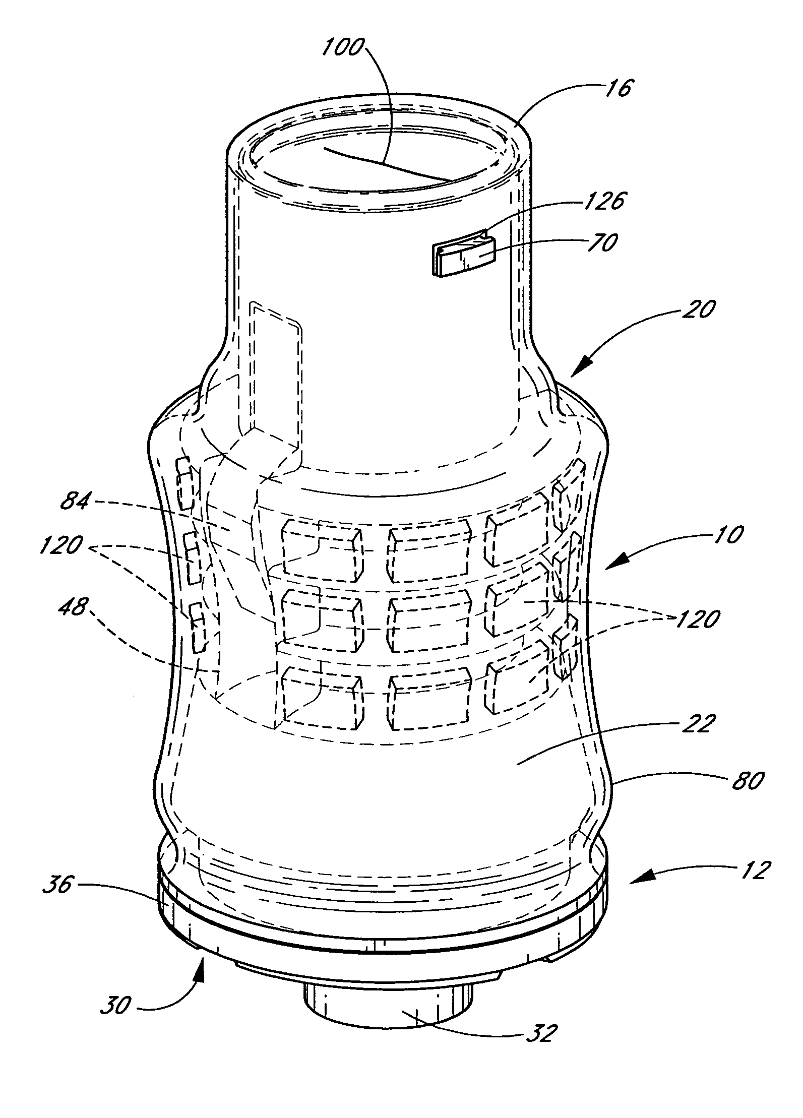
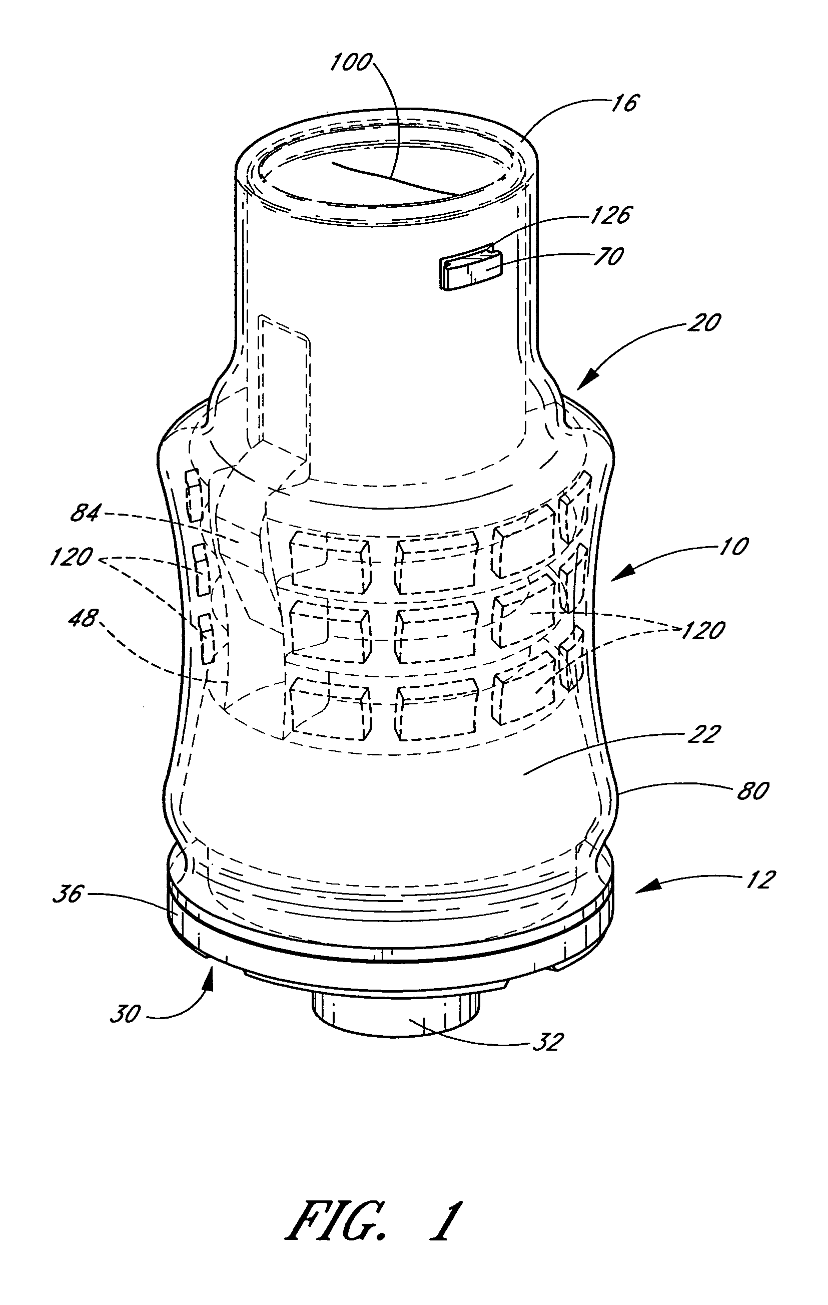
[0051] Referring now to FIG. 1, the illustrated embodiment of a medical connector 10 comprises a substantially rigid housing 12 with a flexible member 80 that has been stretched over the outer surface of the housing 12 to provide a soft, grippable outer surface 22. A slit opening 100 is formed at an upstream end 16 of the flexible member 80. The upstream end of the flexible member 80 surrounding the housing 12 provides a surface that is easily cleaned, and is substantially free from cavities or recesses in which contaminants may...


PUM

PropertyMeasurementUnit
movementaaaaaaaaaa
flow rateaaaaaaaaaa
inner diameteraaaaaaaaaa

Abstract

A soft grip medical connector comprises a housing with an upstream end, a downstream end and a lumen extending through a central portion thereof. A flexible member comprises a valve portion integrally formed with a sleeve portion. The valve portion is positioned within a section of the housing and is configured to control a flow of fluid through the housing lumen. The sleeve is inverted to envelope at least a portion of the outer surface of the housing. In some embodiments the gripping portion is integrally formed with the valve portion. In some embodiments, the connector is also generally configured to create a positive pressure in a catheter lumen upon removal of a syringe or other medical device from the upstream end of the connector. Methods of making a medical fluid connector generally comprise forming a valve member with a sleeve extending there from, and assembling the valve, sleeve and housing.

Description

CROSS-REFERENCE TO RELATED APPLICATIONS [0001] This application is a continuation of U.S. patent application Ser. No. 11 / 267,822, filed Nov. 4, 2005, pending, which claims the benefit of U.S. Provisional Application No. 60 / 625,644, filed on Nov. 5, 2004, and U.S. Provisional Application No. 60 / 654,250, filed on Feb. 18, 2005, the entireties of which are hereby incorporated by reference.BACKGROUND OF THE INVENTIONS [0002] 1. Field of the Invention [0003] The inventions disclosed herein relate in general to the field of medical connectors, and in particular to needle-less medical connectors. [0004] 2. Description of the Related Art [0005] The manipulation of fluids for parenteral administration in hospitals and medical settings routinely involves the use of connectors for selectively facilitating the movement of fluids to or from patients. For example, a connector may be attached to a catheter that leads to a tip positioned within a patient, and various connectors may be attached to o...

Claims


Application Information

Patent Timeline
Patent Type & Authority Applications(United States)
IPC IPC(8): A61M5/00
CPCA61M39/045A61M39/26Y10T29/49826A61M2039/266A61M39/10A61M2039/263A61M39/22A61M2205/02A61M2205/586
Inventor FANGROW, THOMAS F.
Owner FANGROW THOMAS F
Why Eureka
Try Eureka