Traction cleat and receptacle
- Summary
- Abstract
- Description
- Claims
- Application Information
AI Technical Summary
Benefits of technology
Problems solved by technology
Method used
Image
Examples
Embodiment Construction
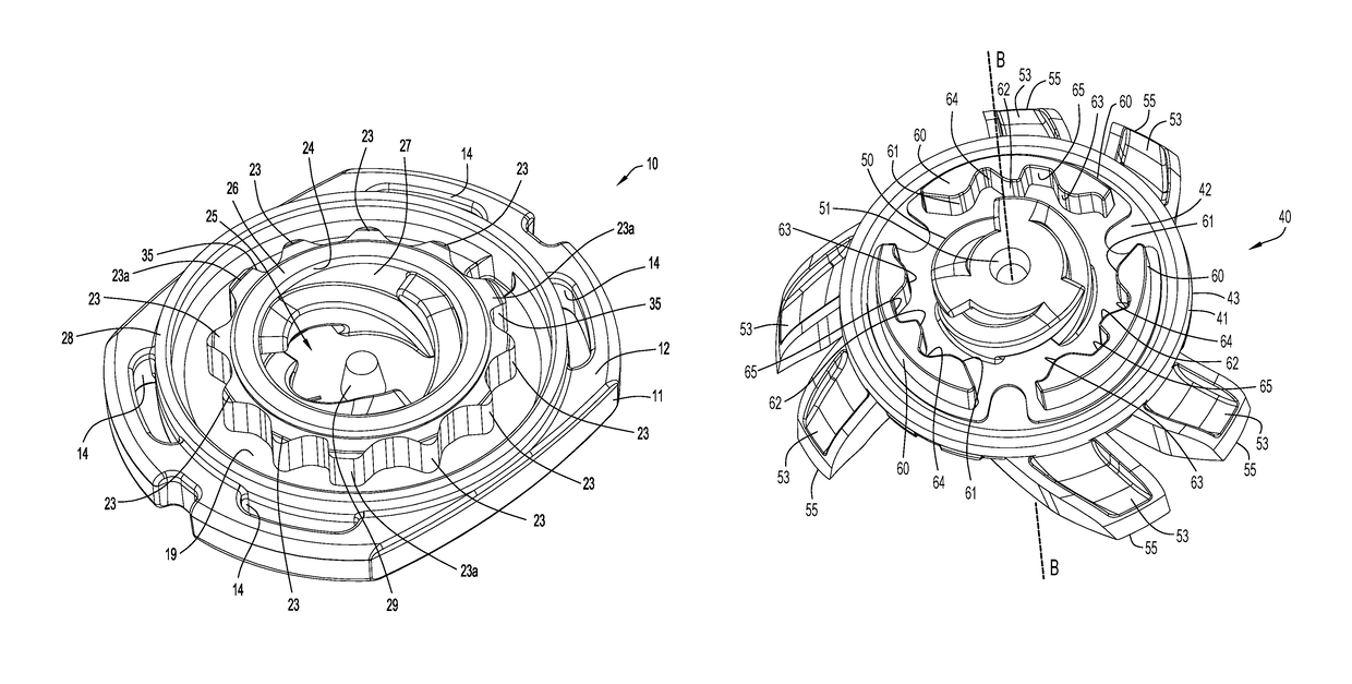
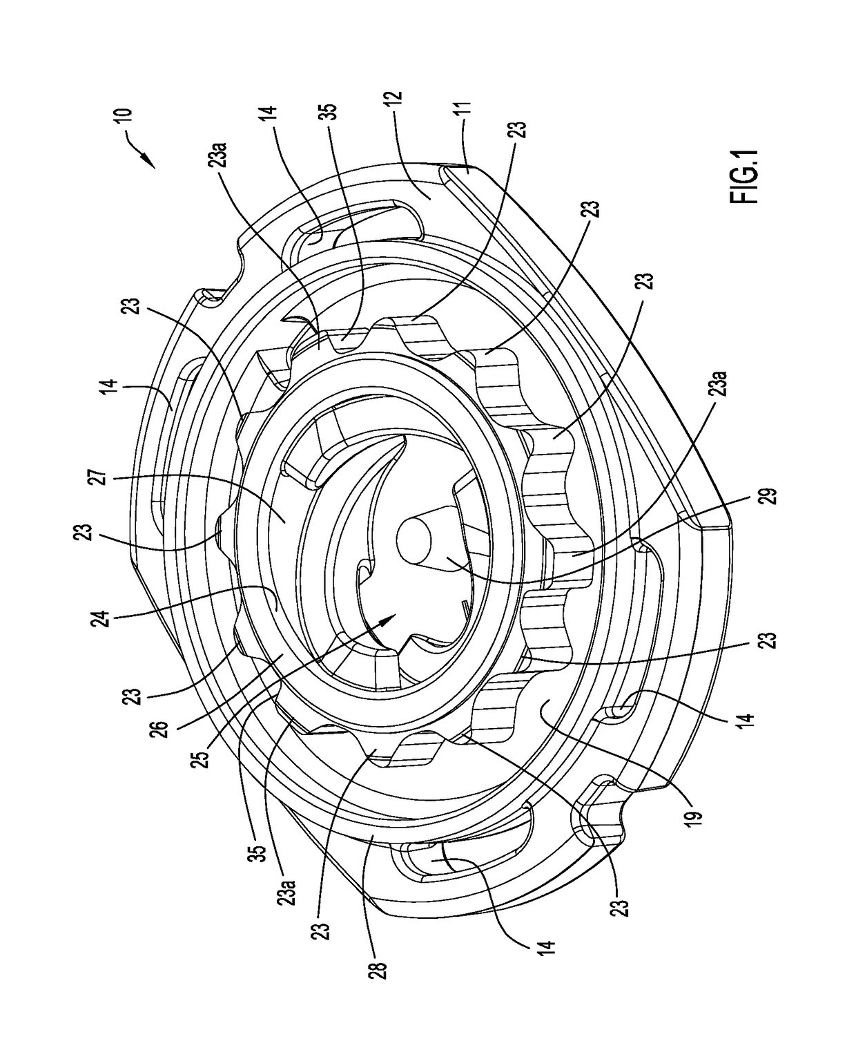
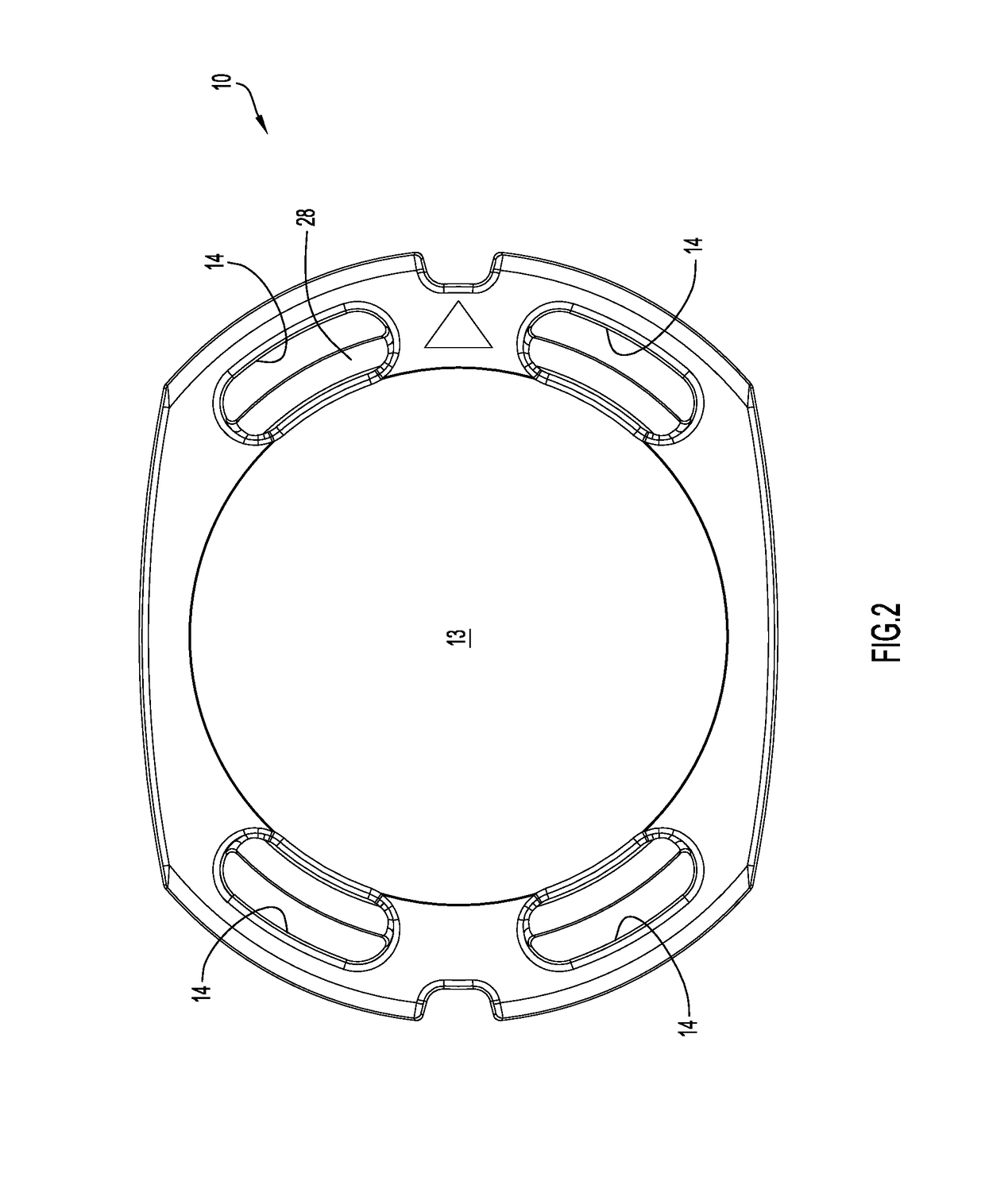
[0038]Referring to FIGS. 1-9 in greater detail, there is illustrated a receptacle 10 (FIGS. 1-5) configured to receive, engage and securely lock in place the cleat 40 (FIGS. 6-9). Receptacle 10 includes a base plate 11 having a bottom surface 12 and a top surface 13. The base plate 11, as illustrated, may be generally rectangular with slightly rounded (i.e., large radius of curvature) opposed long side edges and more rounded (i.e., smaller radius of curvature) opposed shorter side edges; however, the base plate configuration itself is not of itself a feature of the invention and can be otherwise configured, symmetrically or asymmetrically about receptacle attachment axis A. When cleat 40 is installed in receptacle 30, cleat axis B and receptacle axis A are coaxially positioned.
[0039]The radially outer portions of base 11 proximate each short side edge have two mounting slots 14 defined longitudinally therethrough (i.e., through the thickness of the base plate) for securing the recep...
PUM
 Abstract
Description
Claims
Application Information
 - R&D
- Intellectual Property
- Life Sciences
- Materials
- Tech Scout
- Unparalleled Data Quality
- Higher Quality Content
- 60% Fewer Hallucinations
Browse by: Latest US Patents, China's latest patents, Technical Efficacy Thesaurus, Application Domain, Technology Topic, Popular Technical Reports.
© 2025 PatSnap. All rights reserved.Legal|Privacy policy|Modern Slavery Act Transparency Statement|Sitemap|About US| Contact US: help@patsnap.com


