Device, arrangement and method for verifying the operation of electricity meter
What is Al technical title?
Al technical title is built by PatSnap Al team. It summarizes the technical point description of the patent document.
a technology of electricity meters and devices, applied in the field of electricity and electric power distribution, can solve the problems of requiring more complex electricity meters, consuming considerable amounts of electricity including electricity, and scale processes and related machinery may naturally consume considerable amounts of energy including electricity, and even a vague conclusion takes considerable time to reach
Active Publication Date: 2017-10-24
LANDIS & GYR AG
View PDF11 Cites 1 Cited by
Summary
Abstract
Description
Claims
Application Information
AI Technical Summary
This helps you quickly interpret patents by identifying the three key elements:
Problems solved by technology
Method used
Benefits of technology
[0010]The objective is to alleviate one or more problems described hereinabove and not yet satisfactorily addressed by the known arrangements, and to provide a feasible option for validating the measuring accuracy of an electricity meter.
Problems solved by technology
In contrast, with industrial environments different large-scale processes and related machinery may naturally consume considerable amounts of energy including electricity.
More complex charging schemes require also more complex electricity meters.
Based on a detected anomaly in the electricity consumption figures, meter malfunction may be certainly suspected as one possible explanation, but reaching even such a vague conclusion takes considerable amount of time.
Such procedures require vast amounts of manual labor, are tedious and still a good number of faulty meters may remain in use, i.e. the obtained level of certainty is not satisfactory when fault-free, validated operation of basically every electricity meter, not just some percentage thereof, is desired.
Method used
Image
Click on the blue label to locate the original text in one second.
Reading with bidirectional positioning of images and text.
Examples
Embodiment Construction
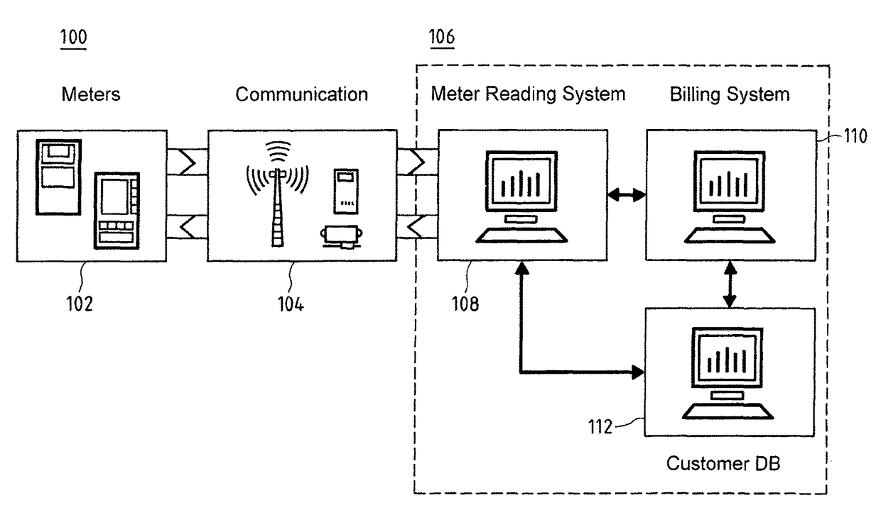
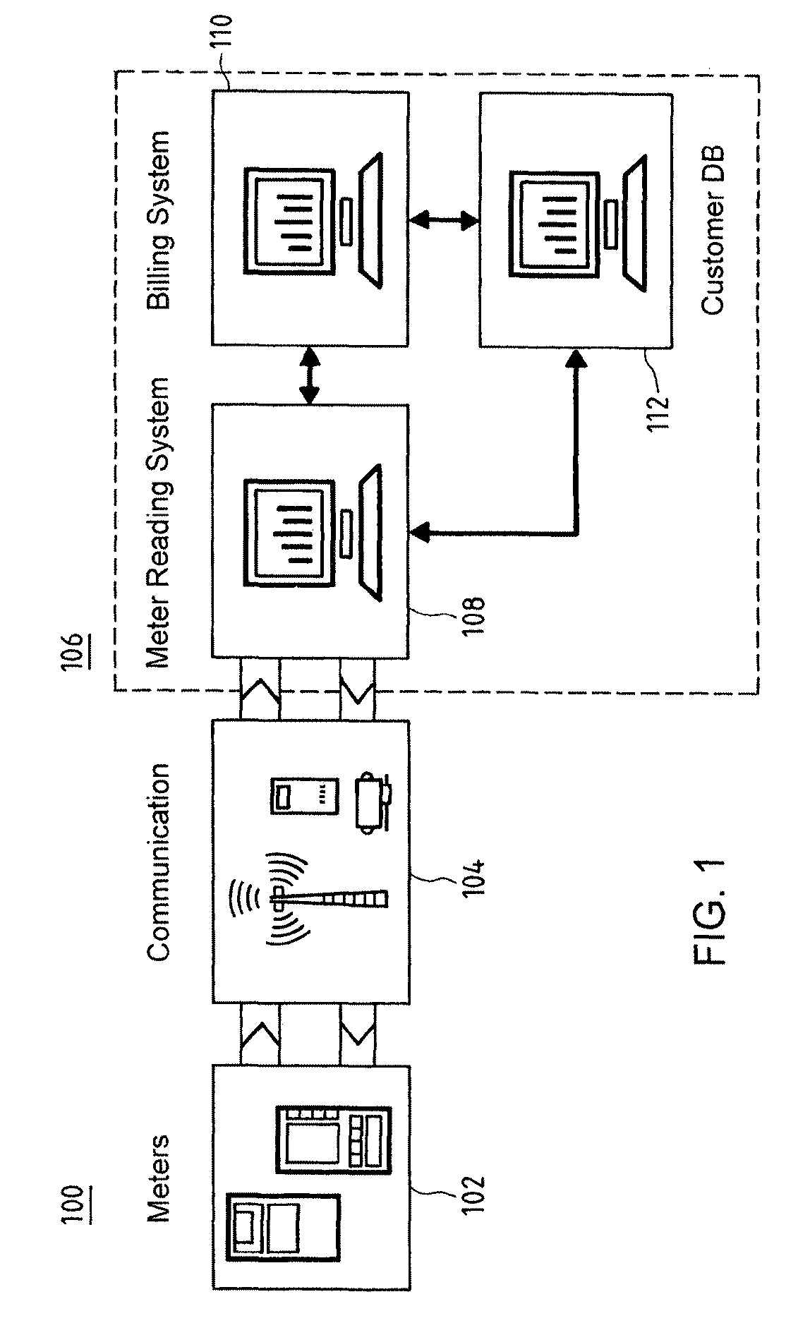
[0045]FIG. 1a is a sketch illustrating, at 100, a potential use scenario and a plurality of related entities regarding different embodiments of the present invention.
[0046]A number of electricity meters 102 may be connected via a number of communication paths 104 such as communications or at least communications-enabling, such as power, networks to a remote system 106 operated by electric utility, for example, and containing among other potential elements e.g. a meter reading systern 108, a billing system 110 and a customer database 112 that are at least functionally mutually connected.
[0047]The electricity meters 102 utilized in connection with the present invention may differ depending on the use scenario and related needs. They may measure power and preferably also energy (power integral) according to predetermined standards regarding e.g. AC / DC current and the phase configuration in connection with AC current (single phase vs. polyphase such as two- or three-phase). In case of p...
PUM
Abstract
An electronic electricity meter (102) for monitoring electrical power consumption due to a plurality of loads, comprising electric power sensor (506A, 506, 502, 504, 508) configured to register, optionally in a substantially real-time fashion, data indicative of aggregate power demand (202) of a number of loads coupled to a common electrical power source, such as one or more phases of a polyphase system, load tracker (506B, 506, 502, 504) configured to detect the effect of individual loads on the basis of distinctive load patterns in said data, wherein the tracker is configured to utilize a distinctive load pattern detected in said data as at least a basis for a reference pattern (304, 306, 308) for subsequent detections (304a, 306a, 308a) of the effect of the same load in the data, accuracy analyzer (506C, 506, 502, 504) configured to, on the basis of comparisons of subsequent detections with the corresponding references, determine (312, 314, 316) whether the comparisons relating to at least two, preferably three, loads each indicate the difference between the subsequently detected pattern and the corresponding reference exceeding a predetermined threshold, and notifier (506D, 506, 502, 504, 508) configured to send, provided that positive determination has taken place (318), a notification signal indicative of potential fault with the electricity meter towards an external entity (106, 108). Corresponding arrangement and method are presented.
Description
FIELD OF THE INVENTION[0001]Generally the present invention pertains to electricity and electric power distribution. In particular, the invention relates to monitoring and verifying the operation of the electricity meters.BACKGROUND[0002]In households, e.g. electric (space) heating, fridge and freezer, boiler, lighting, consumer electronics, ventilation and air-conditioning often represent the biggest loads to the electricity network. In contrast, with industrial environments different large-scale processes and related machinery may naturally consume considerable amounts of energy including electricity. Equally in both scenarios, the energy consumption shall be accurately measured to enable, among other potential uses, appropriate, fair billing thereof, usually based on unit price without forgetting potential other price-affecting factors such as time of the day (tariff).[0003]Contemporary solutions for keeping track of site-specific, such as plant or house-specific, electricity con...
Claims
Application Information
Patent Timeline
Application Date:The date an application was filed.
Publication Date:The date a patent or application was officially published.
First Publication Date:The earliest publication date of a patent with the same application number.
Issue Date:Publication date of the patent grant document.
PCT Entry Date:The Entry date of PCT National Phase.
Estimated Expiry Date:The statutory expiry date of a patent right according to the Patent Law, and it is the longest term of protection that the patent right can achieve without the termination of the patent right due to other reasons(Term extension factor has been taken into account ).
Invalid Date:Actual expiry date is based on effective date or publication date of legal transaction data of invalid patent.