Illumination device with LED with a self-supporting grid containing luminescent material and method of making the self-supporting grid

a technology of luminescent material and illumination device, which is applied in the direction of semiconductor devices for light sources, lighting and heating apparatus, coatings, etc., can solve the problems of complex structure, inability to construct high-power devices, and inability to easily dissipate heat, and achieves low “irradiation” of luminescent materials, less back reflection/reabsorption, and substantial thermal quenching

Inactive Publication Date: 2011-02-24
SIGNIFY HLDG BV
View PDF3 Cites 42 Cited by
  • Summary
  • Abstract
  • Description
  • Claims
  • Application Information

AI Technical Summary

Benefits of technology

[0034]With the proposed illumination device, wherein an exit window is applied, the lamp may look white especially when it is in the off-state or illuminated with white light. Other advantages, especially relative to systems wherein the luminescent material is provided on the LED, may be that an intrinsically efficient system (less back reflection / reabsorption) may be provided and that a warm white option (without substantial thermal quenching and with a relatively “low” irradiation of the luminescent material) may be provided. Further, the illumination device according to the invention is a relatively simple concept (may be based on blue LEDs only, which has the advantage of relatively easy assembly and driving) and, in addition, the option of an adjustable color temperature is feasible.
[0035]Remote luminescent material in LED based light sources seems to be very advantageous with respect to system efficacy, in particular for the generation of light with a low color temperature (warm white). Applying the luminescent material-containing grid as described herein may result in high system efficacy, because only little light is reflected back into the LED where it has a rather high chance of being absorbed. Using the luminescent material remote from the LEDs can result in efficacy gains up to about 50% compared to systems with luminescent material in the LED package.
[0036]Applying a luminescent material layer at the surface, especially the emitting surface (i.e. downstream surface), of an exit window may result in a rather saturated color point of that surface when the lamp is off or when said surface is illuminated with white light. The degree of saturation of the appearing color of the exit window can be reduced by applying, according to the invention, the luminescent material coating on (and / or in) a transmissive carrier located in between the LEDs and a diffusive, translucent material exit window of the illumination device.
[0037]The translucent exit window may act as the virtual emission window (for the further optical system, where the light may be further manipulated for e.g. beam shaping). With an increasing distance between the luminescent material (layer) and the translucent exit window, the saturation of the color of the translucent exit window may be further reduced. Typically, the saturation can be reduced from about 62% to about 50% by separating the luminescent material layer from the translucent exit window with almost zero spacing in between, and can be further reduced to less than about 20% by increasing the spacing.

Problems solved by technology

A disadvantage of some of the prior art systems may be that heat cannot easily be dissipated.
This implies that high-power devices may not be constructed since thermo-sensible luminescent materials and / or organic substrates may be damaged by the high intensity of the radiation (and concomitant heat development, for instance due to Stokes-shift losses).
A further disadvantage of some of the prior art systems is the complex structure or the use of relatively bulky optics, which may not only have a detrimental effect on efficiency, but may also prevent the construction of small devices.
Other disadvantages of some of the prior art systems may be that relatively expensive and / or difficult to produce (transmissive) materials have to be applied.

Method used


Image

  • Illumination device with LED with a self-supporting grid containing luminescent material and method of making the self-supporting grid
  • Illumination device with LED with a self-supporting grid containing luminescent material and method of making the self-supporting grid
  • Illumination device with LED with a self-supporting grid containing luminescent material and method of making the self-supporting grid

Examples


example

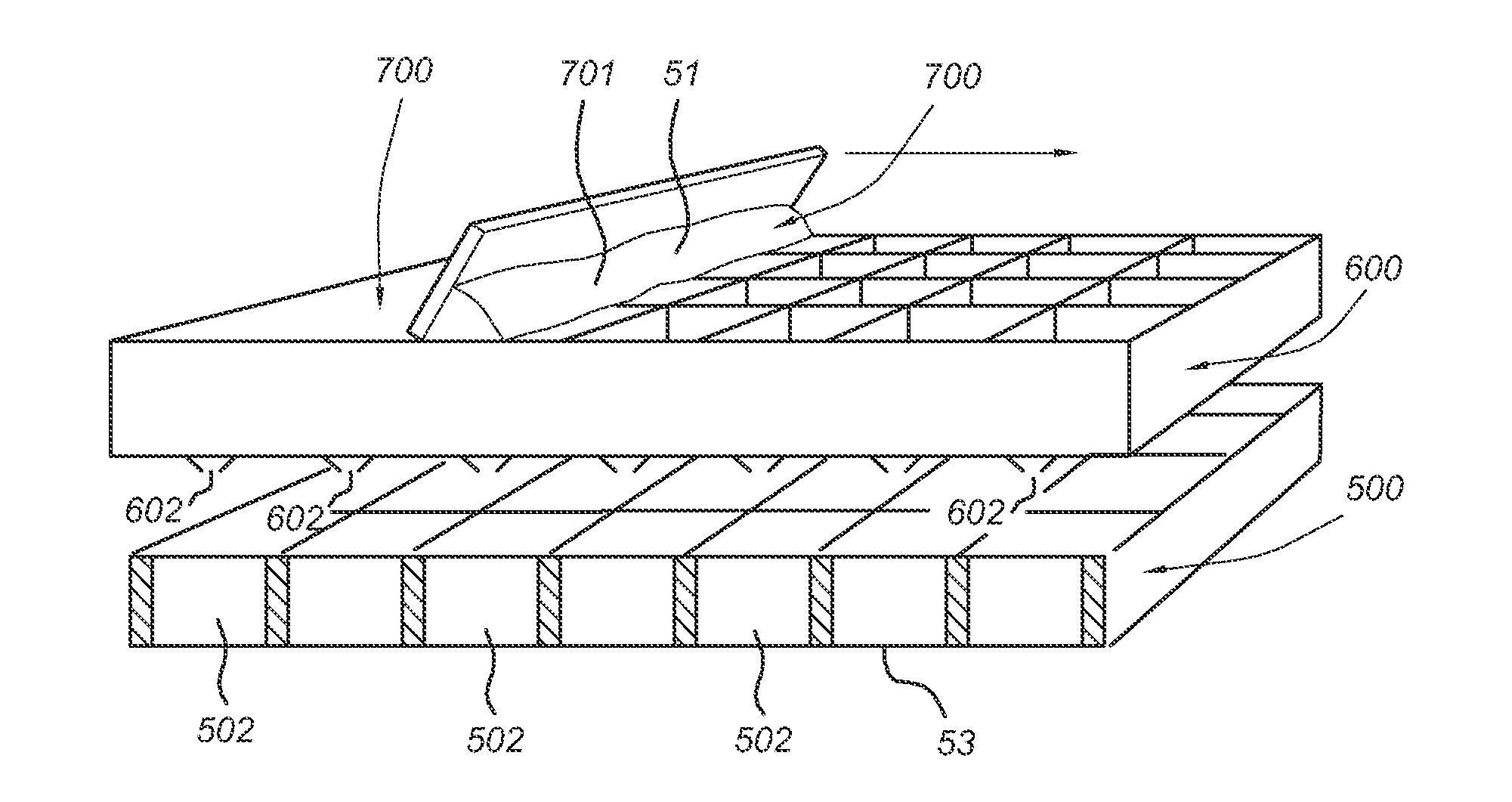
[0114]A metal mesh (made of brass, optical transmission of 70%) was coated (impregnated) with YAG phosphor in organic binder (Neocryl). The phosphor load was 90 g / m2 (the load on the surface irradiated by the blue LEDs amounts to about 70%×90 g / m2=63 g / m2). This phosphor screen was placed on a 455 nm LED test fixture (comprising a heat sink).

An organic film with luminescent material with YAG was also placed on the same test fixture. The phosphor load of the lumifilm was also about 63 g / m2.

[0115]The lumifilm reached a peak temperature of 140° C. The phosphor-coated metal mesh however reached a peak temperature of 110° C. It is very likely that optimization of the metal mesh (the use of metal with higher thermal conductivity, f.i. copper) and optimization of the thermal contact of the metal mesh with the fixture result in even larger temperature differences.

[0116]The term “substantially” used herein, such as in “substantially all emission” or in “substantially consists”, will be under...


PUM


Abstract

The invention provides an illumination device (10) comprising (a) a light emitting diode (LED), (b) a heat sink (85) and (c) a self-supporting grid (500). This grid (500) is arranged downstream of the LED (20) and arranged so as to be in contact with the heat sink 85. The self-supporting grid (500) comprises a plurality of grid structures (501) and a plurality of grid openings 502) between the grid structures (501). At least part of the total number of grid openings (502) encloses luminescent material (51), thereby providing luminescent material-filled grid openings (551). The luminescent material (51) is arranged to absorb at least part of the LED emission (21) and emit luminescent material emission (13). The LED (20) and the luminescent material (51) are arranged to provide light (115) of a predetermined color downstream of the self-supporting grid (500).

Description

FIELD OF THE INVENTION[0001]The invention relates to an illumination device with a self-supporting grid containing luminescent material, as well as to a method of making such a self-supporting grid containing the luminescent material.BACKGROUND OF THE INVENTION[0002]Illumination devices comprising luminescent material for converting LED light are known in the art. Transmissive ceramic layers or luminescent ceramics, which can be used for such applications, and the method of preparation thereof, are also known in the art. Reference is for instance made to US 2005 / 0269582, which discloses a semiconductor light emitting device combined with a ceramic layer which is disposed in a path of light emitted by a light emitting layer. The ceramic layer is composed of or includes a wavelength-converting material such as a luminescent material.[0003]U.S. Pat. No. 7,196,354 discloses another type of device, which comprises a light-generating region adapted to generate light, a wavelength-converti...

Claims


Application Information

Patent Timeline
Patent Type & Authority Applications(United States)
IPC IPC(8): F21V9/16B05D5/06H01L33/50H01L33/64
CPCF21K9/54F21Y2101/02H01L33/508H01L33/644H01L33/507F21K9/56H01L2924/0002F21V9/16F21V7/043F21V29/502H01L2924/00F21K9/62F21K9/64F21Y2115/10F21V9/38F21V13/08F21V9/32
Inventor DEEBEN, JOSEPHUS PAULUS AUGUSTINUSHENDRIKS, RENE JANVAN DER LUBBE, MARCELLUS JACOBUS JOHANNES
Owner SIGNIFY HLDG BV
Why Eureka
Try Eureka