
Output stage for class AB amplifier

a technology of output stage and amplifier, which is applied in the direction of amplifier, amplifier with semiconductor device/discharge tube, amplifier, etc., can solve the problems of high standing power dissipation, low output impedance, no benefit from linearity improvement and low output impedance, etc., to achieve low quiescent current, minimal crossover distortion, and wide operating range

Active Publication Date: 2017-11-14
SNAPTRACK
View PDF13 Cites 0 Cited by
  • Summary
  • Abstract
  • Description
  • Claims
  • Application Information

AI Technical Summary

Benefits of technology

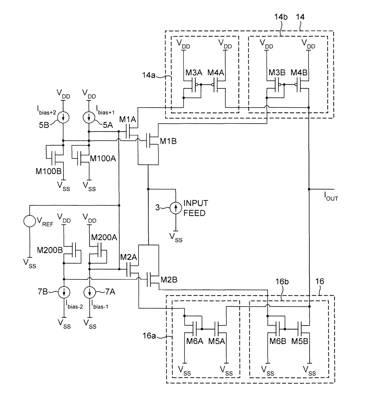
[0023]The invention advantageously provides a Class AB amplifier with a wide operating range and minimal crossover distortion with low quiescent current.

Problems solved by technology

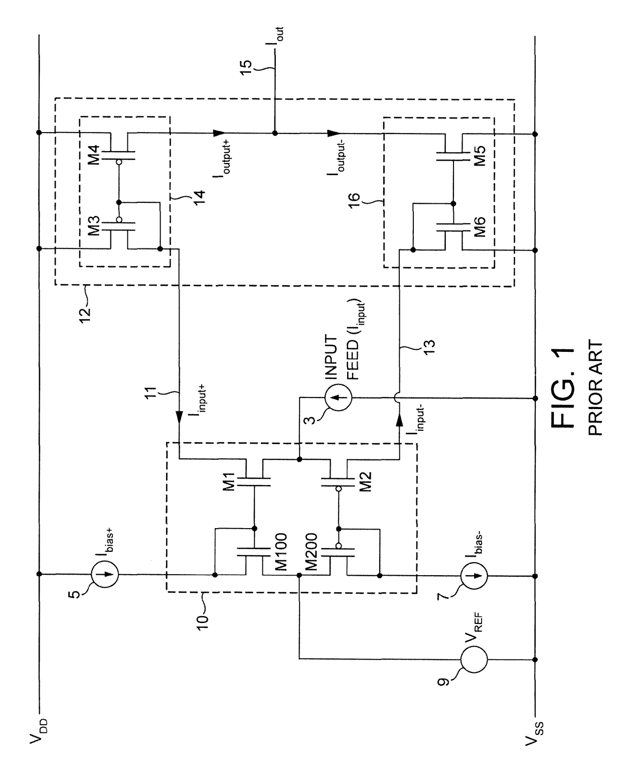
However, if correctly sized to handle large peak-to-mean current swings, a conventional Class amplifier typically requires a large quiescent current.
This arrangement accounts for a high standing power dissipation which is typically observed in many high bandwidth amplifiers.
However, when used as part of the error amplifier in an envelope tracking arrangement (such as an envelope tracking power supply), the second stage 12 must handle a large range of currents, but unfortunately most of the distribution of currents required occurs around the centre of the output waveform exactly where the crossover region is located, and where the currents are relatively small.
Another issue that arises relates to the Gm / C factor.
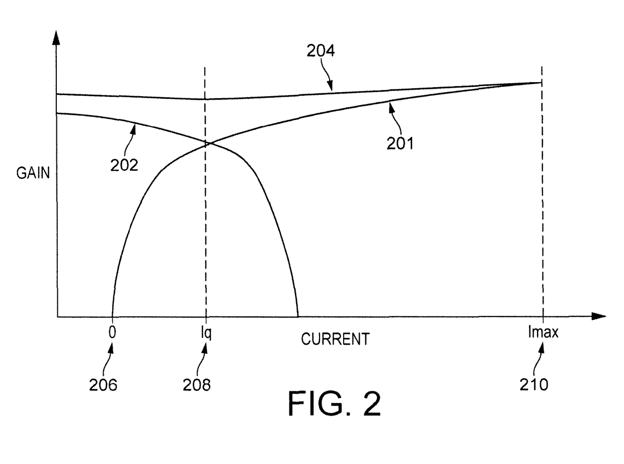
At high currents, the gm / C factor is highest, but since this area of operation (outside the crossover region) is accessed infrequently, there is no benefit obtained from the improved linearity and low output impedance at these currents.
The high Gm / C factor for high currents may further potentially give rise to a problem, because the loop gain of the feedback is pushed up bringing a risk of high frequency instability.

Method used


Image

  • Output stage for class AB amplifier
  • Output stage for class AB amplifier
  • Output stage for class AB amplifier

Examples


Embodiment Construction

[0038]In the following description the invention is described with reference to exemplary embodiments and implementations. The invention is not limited to the specific details of any arrangements as set out, which are provided for the purposes of understanding the invention.

[0039]In general a class amplifier is provided for receiving an input current and for generating amplified output current. The class amplifier has first and second output transmitters connected to provide the output current. In accordance with a described arrangement, if the input current is less than a threshold then the first output transistor is enabled, and a second output transistor is disabled. If the input current exceeds a threshold then the second output transistor is enabled.

[0040]In this way the output current of a class AB amplifier is provided from either physically small or physically large output transistors in accordance with the size of the output current relative to a threshold. The threshold ma...


PUM


Abstract

The invention relates to a class AB amplifier for receiving an input current and generating an amplified output current and having first and second output transistors connected to provide the output current, wherein if the input current is less than a threshold the first output transistor is enabled and the second output transistor is disabled, and if the input current exceeds a threshold the second output transistor is enabled.

Description

BACKGROUND TO THE INVENTION[0001]Field of the Invention[0002]The present invention relates to Class AB amplifiers, and particularly but not exclusively to envelope tracking power supplies incorporating Class AB amplifiers.[0003]Description of the Related Art[0004]Envelope tracking applications may require an error amplifier with the ability to output a wide range of output currents at a high frequency. An example implementation of envelope tracking is an envelope tracking power supply with a switched supply to provide most of the wanted signal energy, and an error amplifier to remove unwanted switching artefacts which provides the remainder of the signal energy. Such an amplifier must have high efficiency, be linear, and must be able to handle high bandwidth signals.[0005]Typically the error amplifiers of such implementations are Class AB amplifiers and are required to handle high peak-to-mean current swings. However, if correctly sized to handle large peak-to-mean current swings, a...

Claims


Application Information

Patent Timeline
Patent Type & Authority Patents(United States)
IPC IPC(8): H03F3/18H03F3/30H03F1/02H03F3/21
CPCH03F1/0205H03F1/0216H03F3/3022H03F3/21H03F2200/252H03F3/3028H03F3/345H03F1/0227
Inventor WILSON, MARTIN
Owner SNAPTRACK
Learn More