Powertrain for a vehicle and method for carrying out load changes

a technology for powertrains and vehicles, applied in the direction of electric propulsion mounting, transportation and packaging, gearing, etc., can solve problems such as substantial efficiency losses, and achieve the effect of safe carrying and highest possible efficiency

Active Publication Date: 2017-11-21
ZF FRIEDRICHSHAFEN AG
View PDF19 Cites 18 Cited by
  • Summary
  • Abstract
  • Description
  • Claims
  • Application Information

AI Technical Summary

Benefits of technology

[0006]Consequently, the purpose of the present invention is to propose a drive-train and methods of the type described at the start, with which powershifts can be carried out safely and with the highest possible efficiency.

Problems solved by technology

However, such rotary transmissions give rise to losses that are responsible for substantial efficiency losses, particularly in the case of electric drives.

Method used


Image

  • Powertrain for a vehicle and method for carrying out load changes
  • Powertrain for a vehicle and method for carrying out load changes
  • Powertrain for a vehicle and method for carrying out load changes

Examples


first embodiment

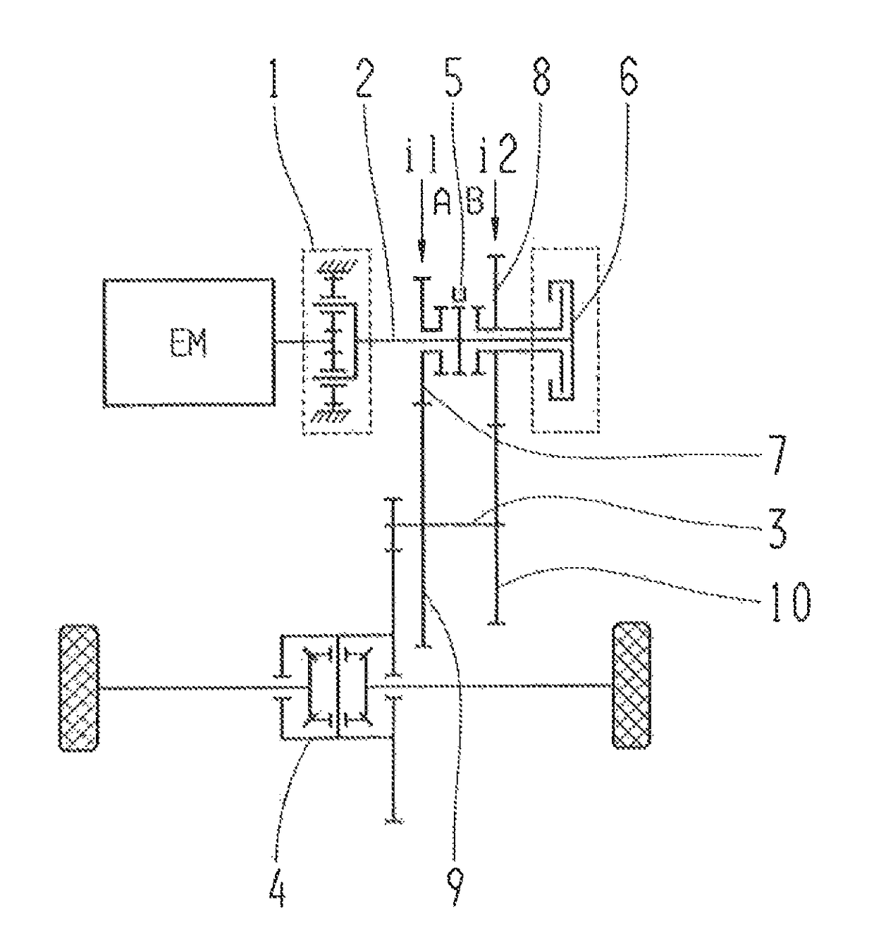
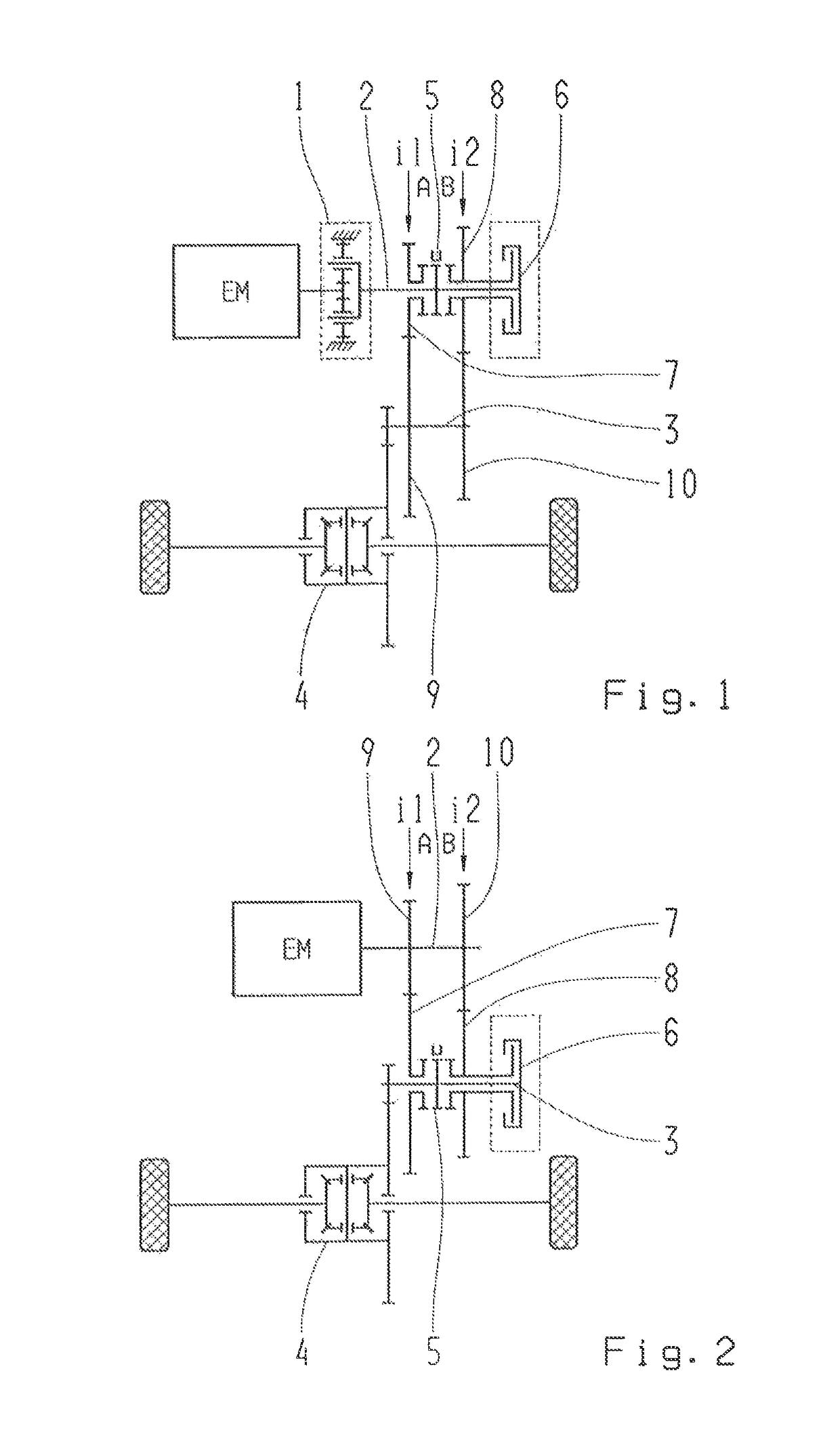
[0027]FIG. 1 shows a first embodiment variant of the drive-train according to the invention, in which the transmission ratio stages i1 and i2 are in the form of spur gear stages. A loose wheel 7 of the first transmission ratio stage i1 and a loose wheel 8 of the second transmission ratio stage i2 are associated with the driveshaft 2 and can be connected to the driveshaft 2 by means of the interlocking shifting element 5.

[0028]In shift position A of the interlocking shifting element 5 the loose wheel 7, and in shift position B the loose wheel 8 is connected to the driveshaft 2. The fixed wheel 9 of the first transmission ratio stage i1 and the fixed wheel 10 of the second transmission ratio stage i2 are connected by way of the intermediate shaft 3 to the drive output differential 4 for driving the drive wheels of the vehicle. By means of the frictional shifting element 6 the loose wheel 8 of the second transmission ratio stage i2 can also be connected to the driveshaft 2 in order to ...

third embodiment

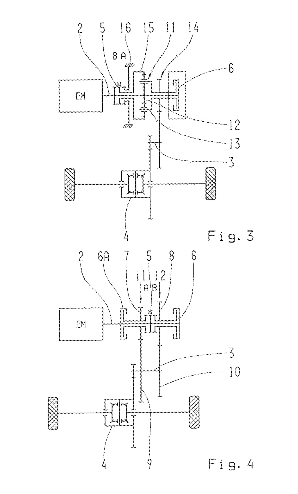
[0032]FIG. 3 shows a third embodiment variant of the drive-train, in which the transmission ratio stages i1, i2 are realized by a planetary gearset 11. The sun gear 12 of the planetary gearset 11 is connected to the driveshaft 2. The planetary carrier 13 of the planetary gearset 11 is connected to a drive output stage 14, which is connected to the drive output differential 4 by way of the intermediate shaft 3. The planetary carrier 13 can also be connected to the driveshaft 2 by means of the frictional shifting element 6. The ring gear 15 of the planetary gearset 11 can be connected by means of the interlocking shifting element 5 to the driveshaft 2 in shift position B or to the housing 16 in shift position A.

[0033]Thus, the two transmission ratio stages i1, i2 are realized by the planetary gearset 11. In this third embodiment variant as well, the second gear can be engaged both by the interlocking shifting element 5 and by the frictional shifting element 6. In this embodiment varia...


PUM


Abstract

A drive-train for a vehicle with at least one electric drive, which can be coupled via a driveshaft (2) to at least a first transmission ratio stage (i1) and a second transmission ratio stage (i2). At least one shifting mechanism is provided for engaging the transmission ratio stages (i1, i2). To carry out powershifts, the shifting mechanism includes at least one interlocking shifting element (5) and at least one frictional shifting element (6, 6A). Each of the transmission ratio stages (i1, i2) can be engaged by the interlocking shifting element (5) and at least one of the transmission ratio stages (i2) can be engaged both by the interlocking shifting element (5) and by the frictional shifting element (6). Methods for carrying out a powershift, between a frictional shifting element (6, 6A) and an interlocking shifting element (5) in the drive-train, are also disclosed.

Description

[0001]This application is a National Stage completion of PCT / EP2014 / 052684 filed Feb. 12, 2014, which claims priority from German patent application serial no. 10 2013 204 227.2 filed Mar. 12, 2013.FIELD OF THE INVENTION[0002]The present invention concerns a drive-train for a. In addition the invention concerns methods for carrying out a powershift between a frictional shifting element and an interlocking shifting element, in particular in the drive-train according to the invention.BACKGROUND OF THE INVENTION[0003]Drive-trains with automated transmissions are known, that use interlocking shifting elements with which, however, only shifts with traction force interruption are possible. In addition drive-trains with powershift transmissions such as dual-clutch transmissions and automatic transmissions are known, in which frictional shifting elements are used in order to carry out shifts while maintaining the traction force.[0004]For example, from the document DE 199 17 724 A1 a drive-t...

Claims


Application Information

Patent Timeline
Patent Type & Authority Patents(United States)
IPC IPC(8): F16H3/08F16H3/48F16H3/091F16H3/54F16H3/12F16H61/04B60K1/00F16H37/08F16H3/089
CPCF16H37/0813F16H3/08F16H3/091F16H3/12F16H3/48F16H3/54F16H61/0403B60K1/00F16H2306/50B60K2001/001F16H3/089F16H2003/0818F16H2003/0826F16H2061/0407F16H2061/047F16H2061/0474F16H2200/0021F16H2200/0034F16H2200/2005F16H2200/2007F16H2200/2033F16H2200/2064F16H2200/2094F16H2306/46F16H37/046F16H37/0833
Inventor KALTENBACH, JOHANNESREISCH, MATTHIASKEHR, ULRICHPREU.BETA., MICHAELBORNTRAGER, KAI
Owner ZF FRIEDRICHSHAFEN AG
Why Eureka
Try Eureka