Ultrasonic motor

a technology of ultrasonic motor and guide rail, which is applied in the direction of generator/motor, piezoelectric/electrostriction/magnetostriction machine, electric apparatus, etc., can solve the negative effect of x-direction movability of oscillator and oscillator holding device, and the inability to smooth the movement of the oscillator holding device inside the guide rail, etc., to achieve simple and inexpensive guidance, precise

Inactive Publication Date: 2017-12-05
PHYSIK INSTR PI
View PDF14 Cites 1 Cited by
  • Summary
  • Abstract
  • Description
  • Claims
  • Application Information

AI Technical Summary

Benefits of technology

[0006]It is therefore the object of the present invention to provide an ultrasonic motor having a holding device for an ultrasonic actuator that overcomes the disadvantages previously mentioned and known from the prior art, wherein it is possible in particular to provide precise, reliable guidance for the holding device and therewith for the ultrasonic actuator as well, simply and inexpensively.

Problems solved by technology

The adjustment operation also requires a great deal of time and experience, since incorrect or inaccurate positioning of the adjusting screws can cause the housing to be bent out of shape, which in turn has a negative effect on the movability of the oscillator and oscillator holding device in the x-direction.
If the housing is bent out of shape, the position of the guide rails too is shifted correspondingly, and smooth movement of the oscillator holding device inside the guide rails is rendered practically impossible.
A further drawback associated with DE 196 48 726 A1 is that considerable effort is required at the manufacturing stage to effectively prevent movement of the oscillator holding device and thus also of the oscillator in the z-direction.
On the other hand, given that the tolerances are so close, even the slightest deformations of the housing and the consequent changes in position of the guide rails will obstruct movement in the x-direction.
The preceding is intended to illustrate that the adjustment by means of the aligning or adjusting screws is of essential importance in the case of DE 196 48 726 A1, and is correspondingly time-consuming and expensive.

Method used


Image

  • Ultrasonic motor
  • Ultrasonic motor
  • Ultrasonic motor

Examples


Embodiment Construction

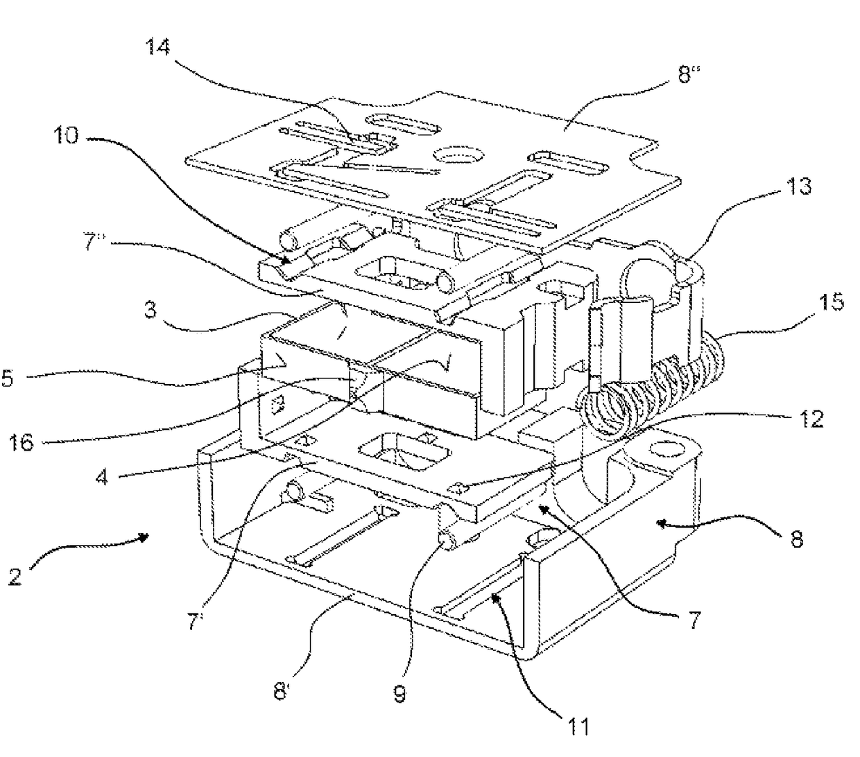
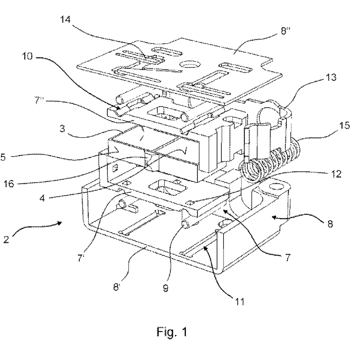
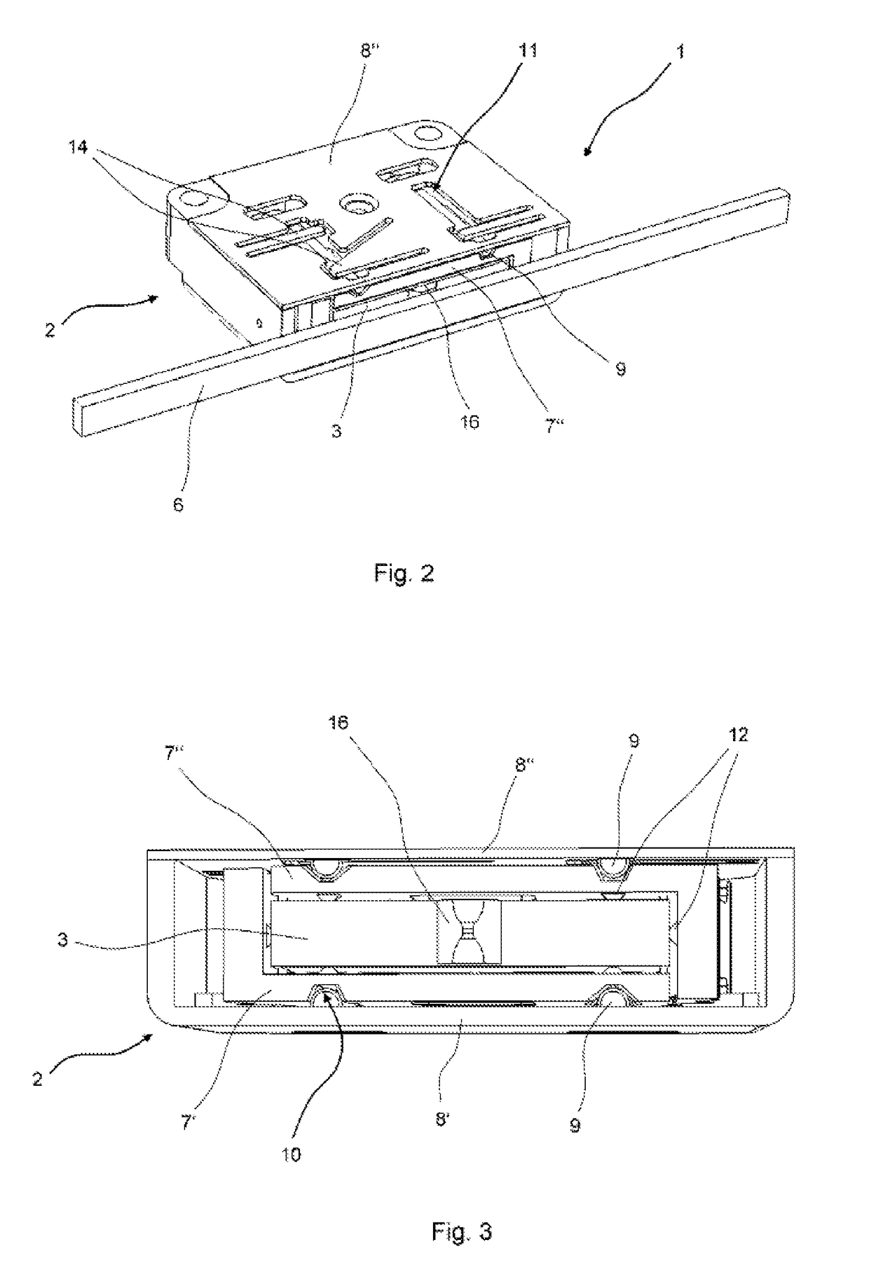
[0029]An exploded view of an embodiment of the holding device for the ultrasonic motor according to the invention is illustrated in FIG. 1. The driven element of the ultrasonic motor is not shown here. The bracket 2 comprises a first frame 7 and a second frame 8. The first frame 7 is made from plastic and comprises two identically shaped, unitary parts 7′ and 7″ with an L-shaped geometry, while the second frame 8 is made of machined aluminium, and comprises two, unitary parts 8′ and 8″ that are shaped differently from one another.

[0030]A piezoelectric ultrasonic actuator 3 having two main surfaces 4 and four side surfaces 5 is clamped inside the first frame 7, and is supported on pyramid-shaped bearing points 12, which are integral with the first frame 7. The pyramidal bearing points 12 are arranged in such manner that damping of the ultrasonic actuator 3 is minimised.

[0031]A friction element 16 made from wear-resistant ceramic material and arranged on a free side surface 5 is provi...


PUM


Abstract

The invention relates to an ultrasonic motor having a bracket, a plate-shaped ultrasonic actuator arranged in the bracket, said ultrasonic actuator having two opposing main surfaces and at least four side surfaces connecting the main surfaces to one another, and an element to be driven, wherein the ultrasonic actuator is pressed against the element to be driven, and the bracket comprises a first frame that supports the ultrasonic actuator and a second frame in which the first frame is supported and guided by bearing elements, and the bearing elements are pressed elastically against the first frame by the second frame. According to the invention, the first frame is pressed against the main surfaces of the ultrasonic actuator via the bearing elements, thus preventing or reducing movements of the ultrasonic actuator in a direction vertical to the main surfaces.

Description

FIELD OF THE INVENTION[0001]The invention relates to an ultrasonic motor with an ultrasonic actuator arranged in a holding device and an element that is to be driven by the ultrasonic actuator.BACKGROUND OF THE INVENTION[0002]A piezoelectric drive element in which a ceramic piezoelectric oscillator is retained in an oscillator holding device and the oscillator holding device itself is mounted so as to be movable on guide rails inside a housing is known from DE 196 48 726 A1. The oscillator is pressed against an element that is to be driven via a spring, the construction of the device being such that the oscillator is able to move in the direction of the driven element, but movement in both directions perpendicular thereto is to be prevented as far as possible. In this context, the guide rails allow the oscillator and the oscillator holding device almost complete freedom of movement in the direction of the driven element (x-direction), but they are intended to prevent undesirable mov...

Claims


Application Information

Patent Timeline
Patent Type & Authority Patents(United States)
IPC IPC(8): H02N2/02B06B1/06H02N2/00
CPCB06B1/0648H02N2/026H02N2/0055
Inventor ROSENKRANZ, MATHIAS
Owner PHYSIK INSTR PI
Why Eureka
Try Eureka