
Inlet or outlet valve for a pump

Inactive Publication Date: 2007-10-30
CONTINENTAL AUTOMOTIVE GMBH
View PDF30 Cites 2 Cited by
  • Summary
  • Abstract
  • Description
  • Claims
  • Application Information

AI Technical Summary

Benefits of technology

[0006]It is therefore the object of the present invention to provide an inlet or outlet valve for a pump that can, with a simple design that is also simple and cheap to manufacture, in particular effectively prevent the closing body from becoming skewed out of line.
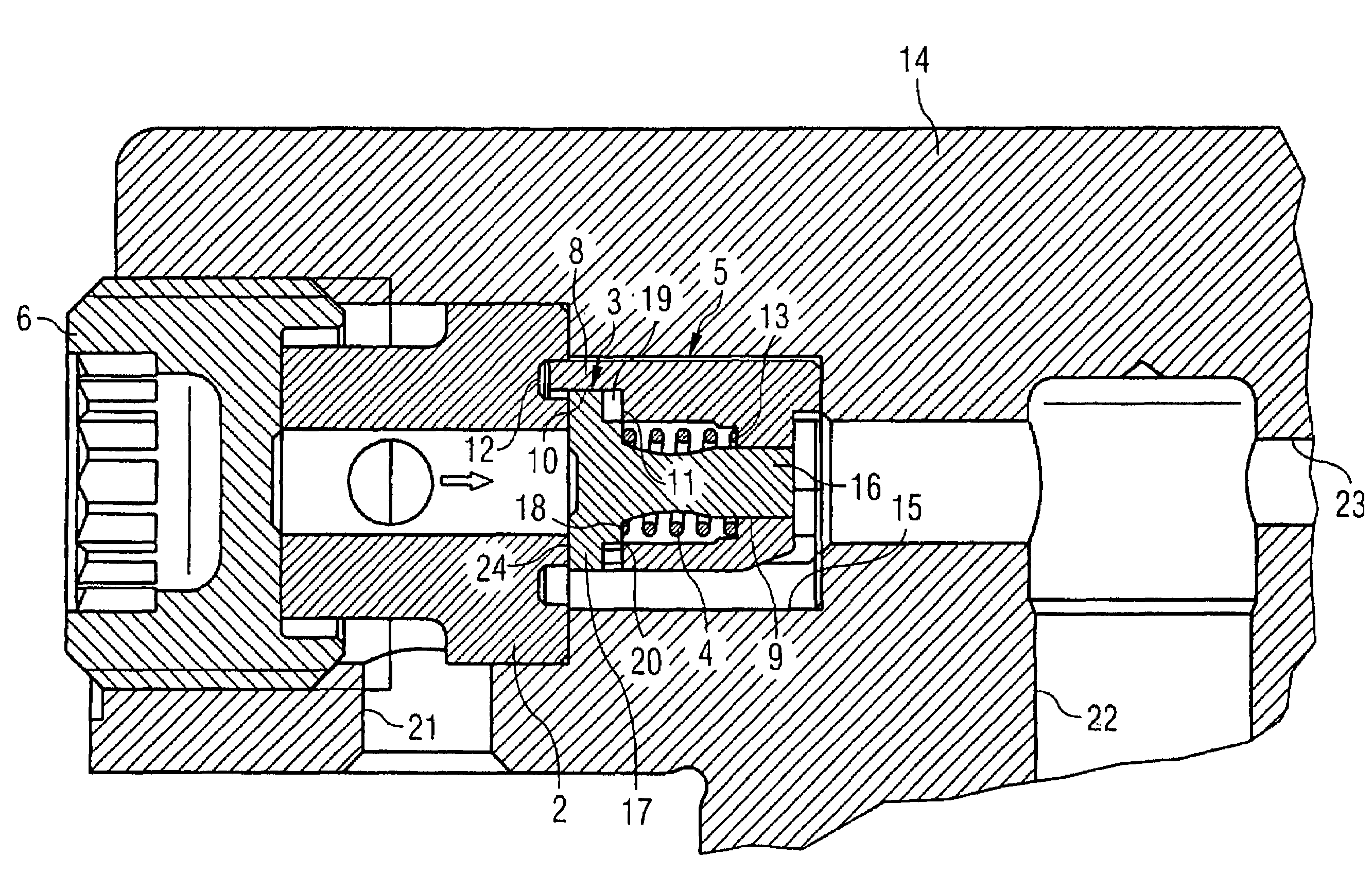
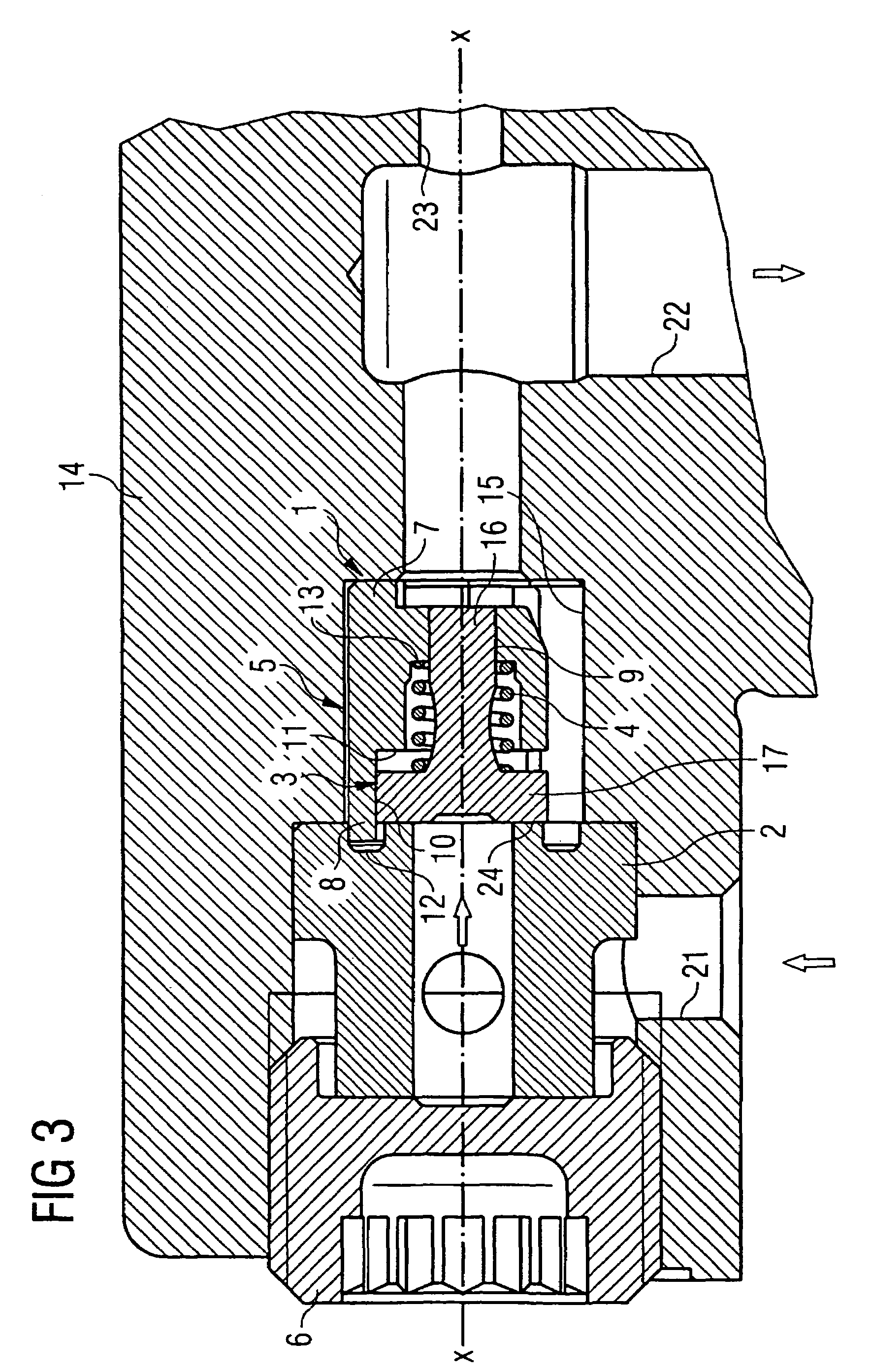
[0009]The axial-flow inlet or outlet valve according to the invention to be used with a pump comprises a closing body, pre-tensioned by a spring element, that can open or close a passage on a valve seat. In addition, the valve comprises a guide element for guiding the closing body. According to the invention, the closing body is guided inside the guide element at least on a first guide area at its upper end region and on a second guide area at its lower end region. By the closing body being guided according to the invention at an upper and a lower end of the closing body, the two guide areas of the closing body are separated as far as possible from each other, so that precise and reliable guidance of a closing body can be achieved in an axial-flow valve for the first time. It is also a reliable means of preventing the closing body from becoming skewed out of line during the opening and closing movement, thereby avoiding unwanted edge stress for the closing body when the closing body comes to rest on the valve seat or against an end-stop surface. In particular this can prevent damage to other valve components so that the valve according to the invention has a particularly long working life. The valve according to the invention is particularly preferred for use in a fuel pump and in particular in a piston fuel pump. Since very high pressures need to be generated by the fuel pump for reservoir injection systems in particular, the dual guidance of the closing body can reliably prevent skewing e.g. during closure of the valve.
[0010]In order to enable the guide element to be manufactured simply and cheaply, the guide element is preferably made of plastic, and particularly preferably is manufactured by means of injection molding. This ensures not only machinability of the guide element but also that the guide element made of plastic can be manufactured cheaply with high production tolerances. In addition, this means that the stresses introduced in the guide element by manufacture and assembly can be reduced to a large extent.
[0013]The guide element is preferably designed as a sleeve having at least two arms integrally formed thereon. This produces a valve with a particularly simple design that in particular enables good transfer flow in the axial direction, yet the valve according to the invention can still be very compact in construction, in particular in the axial direction.
[0018]According to another preferred embodiment of the present invention, one of the two guide areas has a convex construction, the convex shape of the guide area preventing a guide shaft of the closing body from tilting out of line.

Problems solved by technology

In the known axial-flow inlet valves (check valves) of high-pressure pumps it is difficult to guide the closing body precisely because the closing body is seated in a free-moving flange sleeve.
This means that the closing body can become skewed out of line, having a negative impact on seat wear and the operation of the inlet valve, in particular when the pump is running at high speeds.
In addition, the transfer flow through inlet valves having an axial flow direction is often achieved with an unsatisfactory solution and leads to additional losses.

Method used


Image

  • Inlet or outlet valve for a pump
  • Inlet or outlet valve for a pump
  • Inlet or outlet valve for a pump

Examples


Embodiment Construction

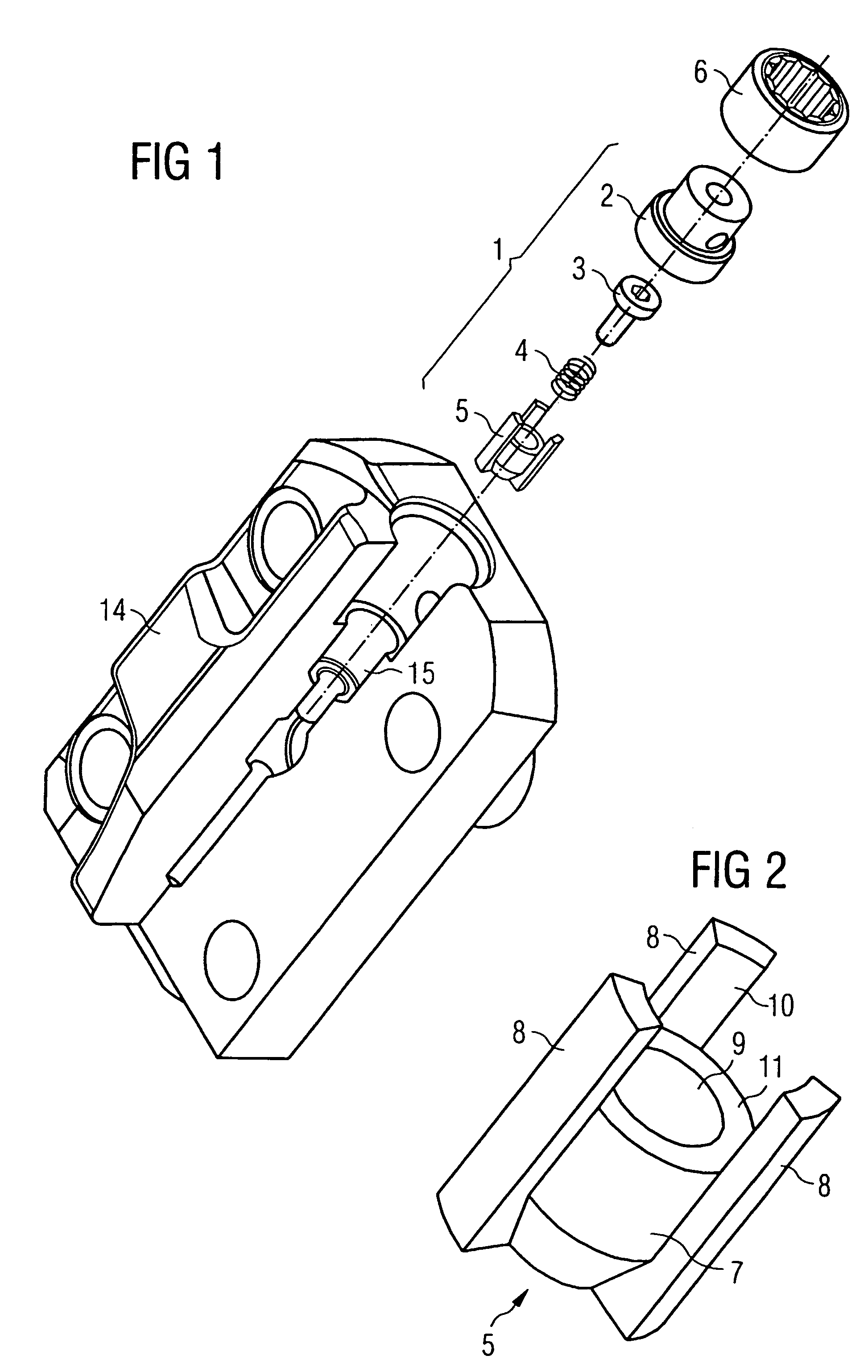
[0028]An inlet valve according to a first exemplary embodiment of the present invention is described below with reference to FIGS. 1 to 3. The inlet valve shown in FIGS. 1 to 3 is used in a radial piston pump that delivers fuel for a reservoir injection system.

[0029]As shown in FIG. 1 in particular, the valve 1 according to the invention comprises a valve seat 2, a closing body 3, a spring element 4 and a guide element 5, where the valve 1 according to the invention is designed such that the aforementioned individual parts can be pre-assembled and then arranged in the pre-assembled state in a recess 15 in a housing 14 of the pump. The pre-assembled valve 1 is fixed in the housing 14 by means of a screw plug 6.

[0030]FIG. 2 shows the guide element 5 in detail. As shown in FIG. 2, the guide element 5 comprises a cylindrical region 7 having an internal through hole and three arms 8 integrally formed around the outer circumference of the cylindrical region 7. The guide element 5 is prefe...


PUM


Abstract

An inlet or outlet valve for a pump comprises a closing body (3) pretensioned by a spring element (4). The closing body (3) can open or close a passage on a valve seat (2). The valve also comprises a guide element (5) for guiding the closing body (3). Inside the guide element (5), the closing body (3) is guided at least on a first guiding area (9) and a second guiding area (10).

Description

CROSS REFERENCE TO RELATED APPLICATION[0001]This application is a continuation of copending International Application No. PCT / DE02 / 04752 filed Dec. 30, 2002 which designates the United States, and claims priority to German application no. 102 00 275.4 filed Jan. 7, 2002.TECHNICAL FIELD OF THE INVENTION[0002]The present invention relates to an inlet or outlet valve for a pump.DESCRIPTION OF THE RELATED ART[0003]Inlet or outlet valves for pumps are known in various embodiments. For example, DE 197 44 577 A1 shows a radial piston pump for high-pressure fuel delivery that has a spring-loaded inlet valve. The inlet valve is arranged in a plate provided with a transverse hole through which fuel can flow during the induction stroke via the opened inlet valve. The inlet valve is also arranged in a recess in a screw plug. The closing body is substantially T-shaped, and a cylindrical section of the closing body is guided in a flange sleeve that is arranged loosely in the recess in the screw p...

Claims


Application Information

Patent Timeline
IPC IPC(8): F16K15/06F16K21/10F02M55/00F02M55/02F04B53/10F16K15/02
CPCF16K15/026F04B53/1027Y10T137/7933Y10T137/7852
Inventor ARNOLD, BERNHARDHOHMANN, MARC
Owner CONTINENTAL AUTOMOTIVE GMBH
Learn More