
Yarn laying equipment and winding machines

A kind of equipment and yarn technology, which is applied in the field of yarn laying equipment, can solve the problems of wing wheel pair yarn loss and loss, etc., and achieve the effect of overcoming the failure or interruption of the winding process

Active Publication Date: 2018-01-02
SSM萨罗瑞士麦特雷有限公司
View PDF11 Cites 0 Cited by
  • Summary
  • Abstract
  • Description
  • Claims
  • Application Information

AI Technical Summary

Problems solved by technology

Too little yarn tension can lead to loss / loss of yarn guidance by the wing wheel

Method used


Image

  • Yarn laying equipment and winding machines
  • Yarn laying equipment and winding machines
  • Yarn laying equipment and winding machines

Examples


Embodiment Construction

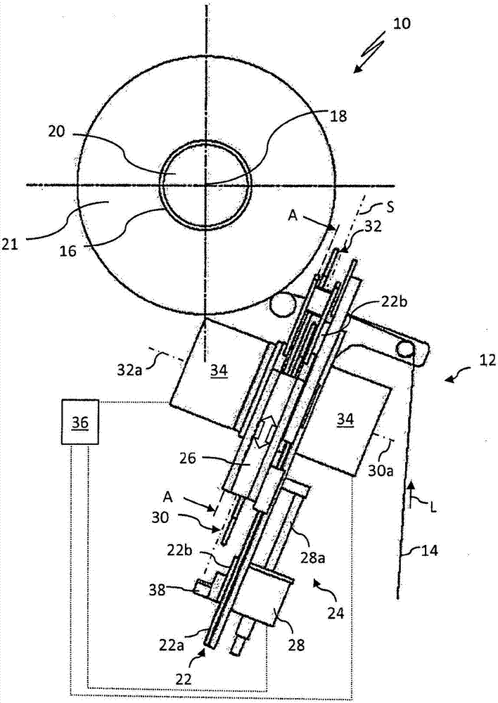
[0027] figure 1 Shown is a partial representation of a winding machine 10 with a laying device 12 for winding a yarn 14 on a bobbin arranged downstream of the laying device 12 in the yarn travel direction L 16 on.

[0028] The bobbin 16 has a bobbin longitudinal axis 18 and is arranged on a bobbin holder 20 . The bobbin holder 20 can be driven circumferentially about the bobbin longitudinal axis 18 of the bobbin 16 . The yarn 14 to be wound can thus be drawn from a feed bobbin (not shown in detail) of the winding machine 10 and wound onto the bobbin 16 to form a yarn package 21 .

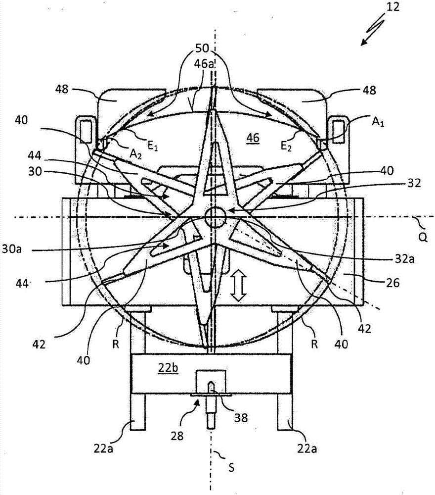
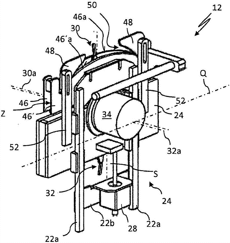
[0029] The yarn laying device 12 has a support frame 22 . The support frame 22 comprises in this example two longitudinal profiles 22 a arranged running parallel to one another, which are connected to each other by two transverse profiles 22 b.

[0030] An adjustment device 24 is arranged on the two longitudinal profiles 22 a of the support frame 22 . The adjustment device 24 includes a (bearin...


PUM


Abstract

The invention relates to a yarn laying device and a winding machine. Yarn laying device for winding yarn onto bobbins, which has two wing wheels which can be driven in opposite directions about their axes of rotation in order to move the yarn to be wound back and forth relative to the bobbin . The yarn laying device has at least one first arc disc, from which the wing wheels protrude at an upper floating point during operation and into which they sink again in the region of the sinking point, The yarn transfer between the wing wheels takes place in the region of the sinking point. Together with the contour of the arc disk, the two yarn tensioners each form a yarn feed slot in the region of the sinking point. The yarn laying device has an adjusting device, by means of which the axes of rotation of the individual wing wheels and the yarn tensioner can be adjusted jointly along the adjusting axis at a constant distance from one another and synchronously with respect to the arc disc. The control device is used to operate the adjustment device in open-loop control / closed-loop control. The winder of the present invention has such a yarn laying device.

Description

technical field [0001] The invention relates to a yarn application device for winding yarn onto bobbins and to a winding machine with such a yarn application device. Background technique [0002] In today's winding machines, yarn laying devices are used which have two wing wheels arranged radially offset from one another, which can be driven in opposite directions about their respective axes of rotation. Such a laying device is known, for example, from EP 0 677 019 B1. The wing wheels overlap each other and generally have two vanes each, which are oriented substantially perpendicularly to the axis of rotation of the wing wheel. The yarn to be wound on the bobbin is guided continuously alternately on the vanes of the one and the other wing wheel during the winding process and can thus be moved relative to the bobbin along its bobbin longitudinal axis in the sense of a reciprocating movement. Back and forth motions in quick sequence. Arc disk or arc plate (so-called yarn gu...

Claims


Application Information

Patent Timeline
Patent Type & Authority Patents(China)
IPC IPC(8): B65H54/28
CPCB65H54/2839B65H54/289B65H2701/31
Inventor M·科里斯特S·沃思
Owner SSM萨罗瑞士麦特雷有限公司
Learn More