Back iron, in particular for an electrical motor and method for producing a back iron for a rotor or stator of an electrical motor

A technology of back iron and rotor is applied in the field of manufacturing such back iron, electromagnetic back iron core, back iron of motor rotor or stator, which can solve the problems of inaccuracy and improve the use characteristics.

Inactive Publication Date: 2014-03-26
HIDRIA BAUSCH
View PDF6 Cites 3 Cited by
  • Summary
  • Abstract
  • Description
  • Claims
  • Application Information

AI Technical Summary

Problems solved by technology

Due to the fact that the individual layers have to be pressed against each other, a certain inaccuracy is created in the outer or inner diameter of the sheet pack

Method used


Image

  • Back iron, in particular for an electrical motor and method for producing a back iron for a rotor or stator of an electrical motor
  • Back iron, in particular for an electrical motor and method for producing a back iron for a rotor or stator of an electrical motor
  • Back iron, in particular for an electrical motor and method for producing a back iron for a rotor or stator of an electrical motor

Examples


Embodiment Construction

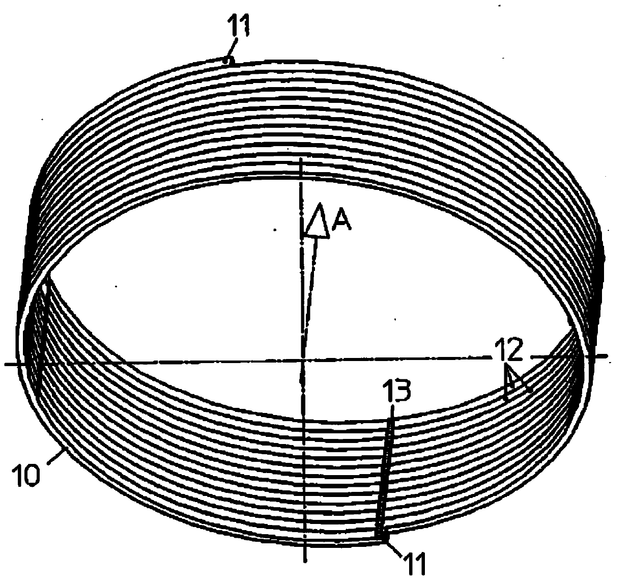
[0028] figure 1 A back iron 10 is shown, ie the electromagnetic back iron core, as it is used for the stator or rotor of an electric machine. In this case, layers 12 of metal strip 40 are wound and form a cylindrical body which encloses an interior. The ends 11 of the metal strip 40 are arranged offset by 180°, so that the end sides of the back iron 10 running transversely to the back iron axial direction A are approximately planarly parallel to one another.

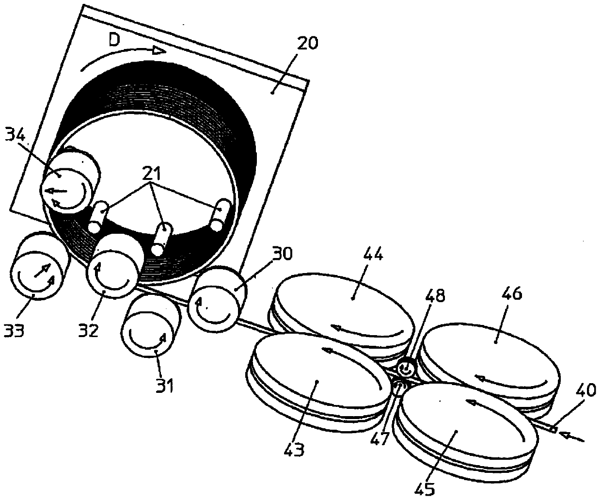
[0029] In order to manufacture the back iron 10, a metal strip 40 is used, such as figure 2 shown is supplied to the winding device.

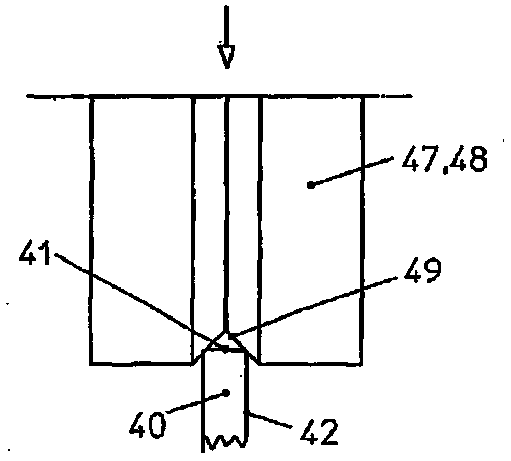
[0030] Figure 4 A cross-sectional view of the metal strip 40 is shown. as from Figure 4 It can be seen that the metal strip 40 has a rectangular cross-section forming vertical and horizontal axes H, Q. FIG. The cross-section is delimited by longitudinal sides 42 and transverse sides 41 . Advantageously, a sheet metal strip, particularly preferably a slotted sheet metal sheet, wh...


PUM


Abstract

The invention relates to a back iron, in particular for a rotor or a stator of an electrical motor, having a plurality of layers made of metal plate or wire, wherein the layers are arranged in a spiral or screw shape. In order to improve the accuracy of the geometry of the backing iron, in particular of the surface lines thereof, according to the invention, the weight of the individual layers is greater than the spring force of the metal plate or metal wire acting between the layers in the back iron axis direction. This is achieved in particular by winding the metal plate or metal wire.

Description

technical field [0001] The present invention relates to a back iron, in particular an electromagnetic back iron core, such as a back iron for motor rotors or stators, which has a plurality of layers consisting of metal plates or wires (hereinafter collectively referred to as metal strips), wherein , the layers are arranged helically or helically. [0002] The invention also relates to a method for manufacturing such a back iron. Background technique [0003] A back iron is known from DE 10 2008 044 097 A1, which is constructed from a plurality of flat metal layers. Here, the flat wire is wound around the cylinder. This results in a cylindrical helix, which is stacked from a plurality of layers of wire. A certain spring pretension exists between the individual layers, so that the layer stack is elastic. It must therefore be pressed together and then fixed. For this purpose, for example, welded connections are used or lacquer materials which cause adhesion are used. Due ...

Claims


Application Information

Patent Timeline
Patent Type & Authority Applications(China)
IPC IPC(8): H02K15/02H02K1/12
CPCH02K1/12H02K15/02
Inventor G·博施R·法斯
Owner HIDRIA BAUSCH
Why Eureka
Try Eureka