Half-iron-core stator pin type winding machine

A technology of iron core stator and winding machine, applied in electromechanical devices, manufacturing motor generators, electrical components, etc., can solve the problems of large occupied area, high production cost, large lateral volume, etc., and achieve convenient disassembly and replacement, and production The effect of low cost and small footprint

Pending Publication Date: 2018-12-07
SANHE IND AUTOMATION EQUIP CO LTD SHUNDE DISTRICT FOSHAN CITY
View PDF11 Cites 3 Cited by
  • Summary
  • Abstract
  • Description
  • Claims
  • Application Information

AI Technical Summary

Problems solved by technology

[0002] The existing half-core stator needle winding machines are winding machines with left and right double winding stations, and the left and right double winding stations require two sets of fixtures for fixing the half-core stator and two Winding mechanism, so the existing half iron core stator needle winding machine has high production cost, large lateral volume and large occupied area, and the winding on the front and rear wire baffles of the half iron core stator needle winding machine The opening is a closed hole, the stator clamp mechanism of the half-core stator needle winding machine can only move back and forth and rotate, the half-core stator cannot be moved up and out of the front and rear wire baffles of the winding machine, and winding cannot be realized
[0003] Therefore, the existing half-core stator needle winding machine does not have the function of processing the end of the wire (that is, the end of the wire is wound on the winding thimble of the stator). Therefore, the existing half-core stator needle winding machine produces For the half-iron core stator, it is still necessary to manually wind the end of the wire on the winding thimble of the stator, but the quality of manual winding is unstable and the efficiency is low

Method used


Image

  • Half-iron-core stator pin type winding machine
  • Half-iron-core stator pin type winding machine
  • Half-iron-core stator pin type winding machine

Examples


Embodiment 1

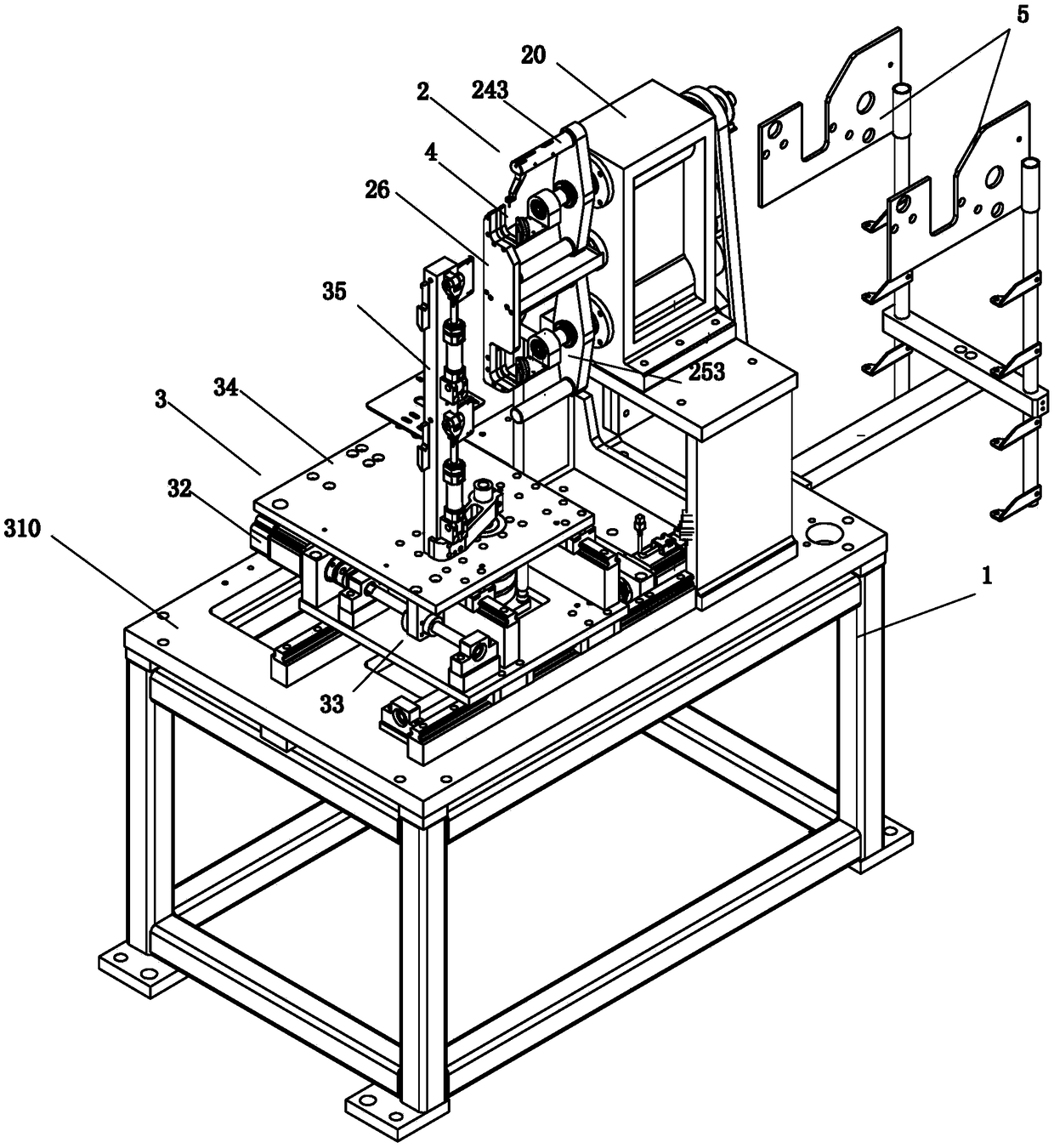
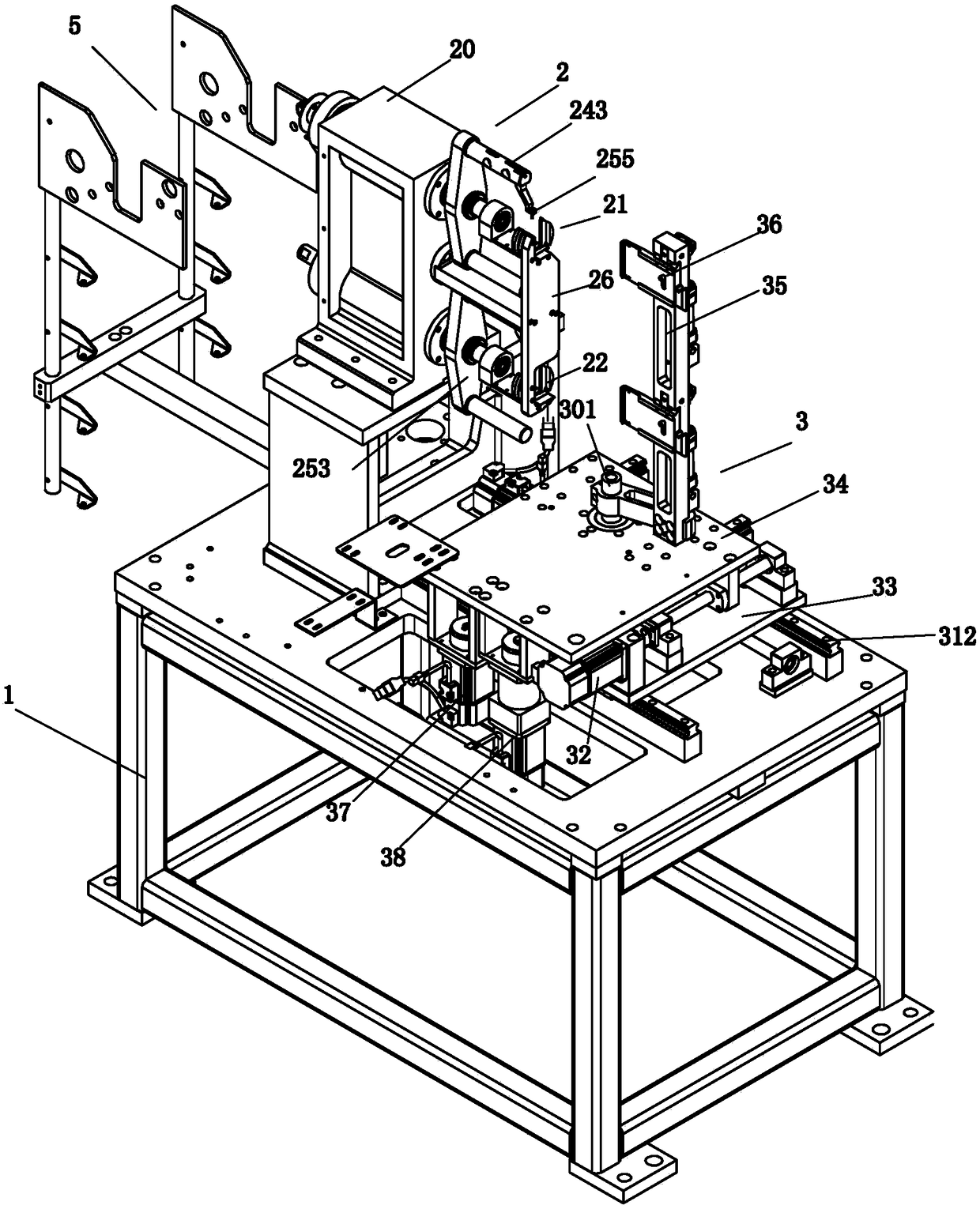
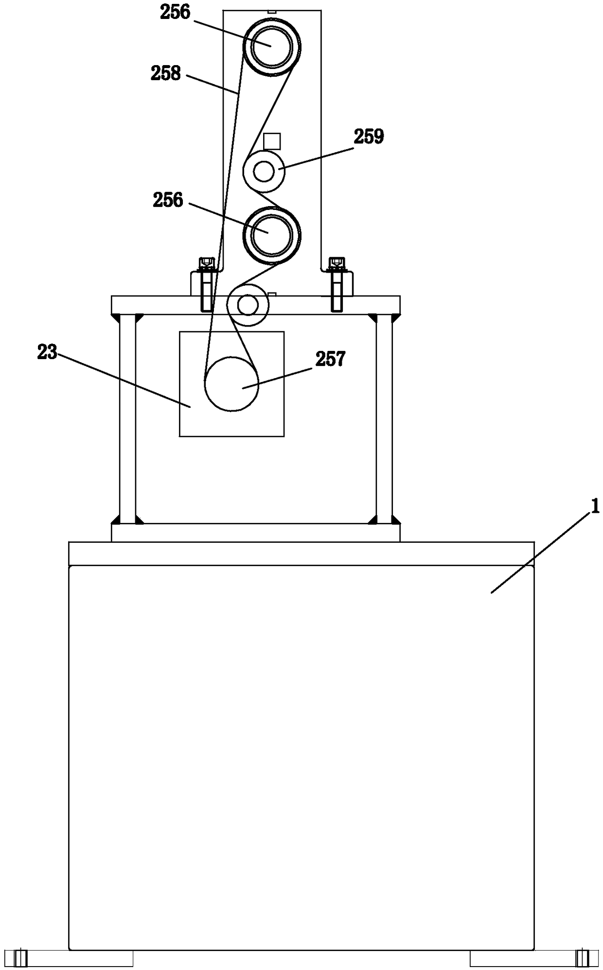
[0060] Embodiment one, see Figure 1 to Figure 16 As shown, a half-core stator needle winding machine includes a frame 1 , a wire tensioner 5 , a winding mechanism 2 , a wire baffle mechanism 4 and a stator clamp mechanism 3 .

[0061] The thread tensioner 5 is arranged on the frame 1 and is located at the rear side of the frame 1 , and is used for tensioning the thread and delivering the thread to the winding mechanism 2 .

[0062] Described winding mechanism 2 is arranged on the frame 1, and is positioned at the front side of frame 1, has upper winding station 21 and lower winding station 22, comprises upper winding rotating shaft and lower winding rotating shaft, upper, The lower winding shaft is horizontally rotated up and down and arranged on the frame 1 for winding the wires on a plurality of wire slots of the half iron core stator 5 .

[0063] The wire baffle mechanism 4 is arranged on the frame 1 and is located on the front side of the frame 1 , and is used to guide t...


PUM


Abstract

The invention relates to a half-iron-core stator pin type winding machine comprising a rack, a line tensioner, a winding mechanism, a wire guiding and baffle mechanism, and a stator clamp mechanism. The winding mechanism is used for winding a wire around a plurality wire grooves of a half-iron-core stator. The wire guiding and baffle mechanism is used for guiding the wire to wind around the plurality wire grooves of the half-iron-core stator. The stator clamp mechanism is used for clamping the half-iron-core stator, driving the half-iron-core stator to move back and forth, left and right, or up and down or rotate, and conveying the half-iron-core stator to the wire guiding and baffle mechanism, so that the winding mechanism carries out winding on the wire grooves of the half-iron-core stator. According to the invention, the double winding stations are set to be an upper winding station and a lower winding station and share the winding motor and the stator clamp mechanism. Therefore, the production cost is lowered; the structure becomes compact; the size is reduced; and the occupied area is reduced.

Description

technical field [0001] The invention relates to the technical field of a stator winding machine, in particular to a half-core stator needle winding machine. Background technique [0002] The existing half-core stator needle winding machines are winding machines with left and right double winding stations, and the left and right double winding stations require two sets of fixtures for fixing the half-core stator and two Winding mechanism, so the existing half iron core stator needle winding machine has high production cost, large lateral volume and large occupied area, and the winding on the front and rear wire baffles of the half iron core stator needle winding machine The opening is a closed opening. The stator clamp mechanism of the half-core stator needle winding machine can only move back and forth and rotate. The half-core stator cannot be lifted out of the front and rear wire baffles of the winding machine, and winding cannot be achieved. [0003] Therefore, the exist...

Claims


Application Information

Patent Timeline
Patent Type & Authority Applications(China)
IPC IPC(8): H02K15/085H02K15/04
CPCH02K15/0435H02K15/085
Inventor 刘晖何小勇
Owner SANHE IND AUTOMATION EQUIP CO LTD SHUNDE DISTRICT FOSHAN CITY
Why Eureka
Try Eureka