Manufacturing method of pneumatic tire

a manufacturing method and tire technology, applied in the field of pneumatic tire manufacturing, can solve the problems of reinforcing cord falling to an outer side, tire performance deterioration, and inability to accurately wound, and achieve the effect of preventing the reinforcing cord from falling

Active Publication Date: 2011-11-08
TOYO TIRE & RUBBER CO LTD
View PDF10 Cites 3 Cited by
  • Summary
  • Abstract
  • Description
  • Claims
  • Application Information

AI Technical Summary

Benefits of technology

[0010]The present invention is made by taking the actual condition mentioned above into consideration, and an object of the present invention is to provide a manufacturing method of a pneumatic tire which can suitably form a spiral belt while using a belt drum having a curvature, and can secure a reinforcing effect of a belt layer.
[0016]In the manufacturing method of the pneumatic tire in accordance with the present invention, the belt layer is formed by a first step, and the belt reinforcing layer is formed by a second step. The belt reinforcing layer is formed as the spiral belt obtained by spirally winding the rubber-coated reinforcing cord, and the end portion in the width direction is arranged in the outer side than the end portion in the width direction of a first belt ply. Accordingly, it is possible to suitably constrain the end portion in the width direction of the belt layer by the belt reinforcing layer, and it is possible to sufficiently secure the reinforcing effect of the belt layer. Further, in the present invention, it is possible to prevent the reinforcing cord from falling down to the outer side near the end portion in the width direction of the belt layer at a time of forming the spiral belt forming the belt reinforcing layer, by arranging a rubber layer protruding to the outer side than the end portion in the width direction of the belt reinforcing layer, in the outer periphery of the end portion in the width direction of the first belt ply, in the first step. As a result, it is possible to accurately wind the reinforcing cord so as to suitably form the spiral belt, while using the belt drum having the curvature.
[0018]In accordance with the structure mentioned above, since the rubber layer is formed by the band-like body extending along the circumferential direction, and the outer peripheral surface thereof is formed by the concavo-convex surface obtained by arranging a plurality of circumferential grooves, it is possible to effectively prevent the reinforcing cord from falling down at a time of forming the spiral belt as the belt reinforcing layer, and it is possible to more suitably form the spiral belt.

Problems solved by technology

However, there is a case that the belt layer generates a local deformation caused by the cord structure mentioned above.
If the cord arrangement is disturbed thereby, there is a case that a dispersion is generated in a rigidity of the tread portion and a tire performance is deteriorated.
Accordingly, there is a problem that the reinforcing cord falls down to an outer side and can not be accurately wound, at a time of forming the spiral belt as described in Japanese Unexamined Patent Publication No. 2002-18977.
As a countermeasure thereof, there can be considered to arrange the end portion in the width direction of the spiral belt in an inner side than the belt layer as described in Japanese Unexamined Patent Publication No. 2003-225953, however, in this case, a constraint force of the end portion in the width direction of the belt layer is reduced, and there is generated a problem that a reinforcing effect by the belt reinforcing layer can not be sufficiently obtained.

Method used


Image

  • Manufacturing method of pneumatic tire
  • Manufacturing method of pneumatic tire
  • Manufacturing method of pneumatic tire

Examples


Embodiment Construction

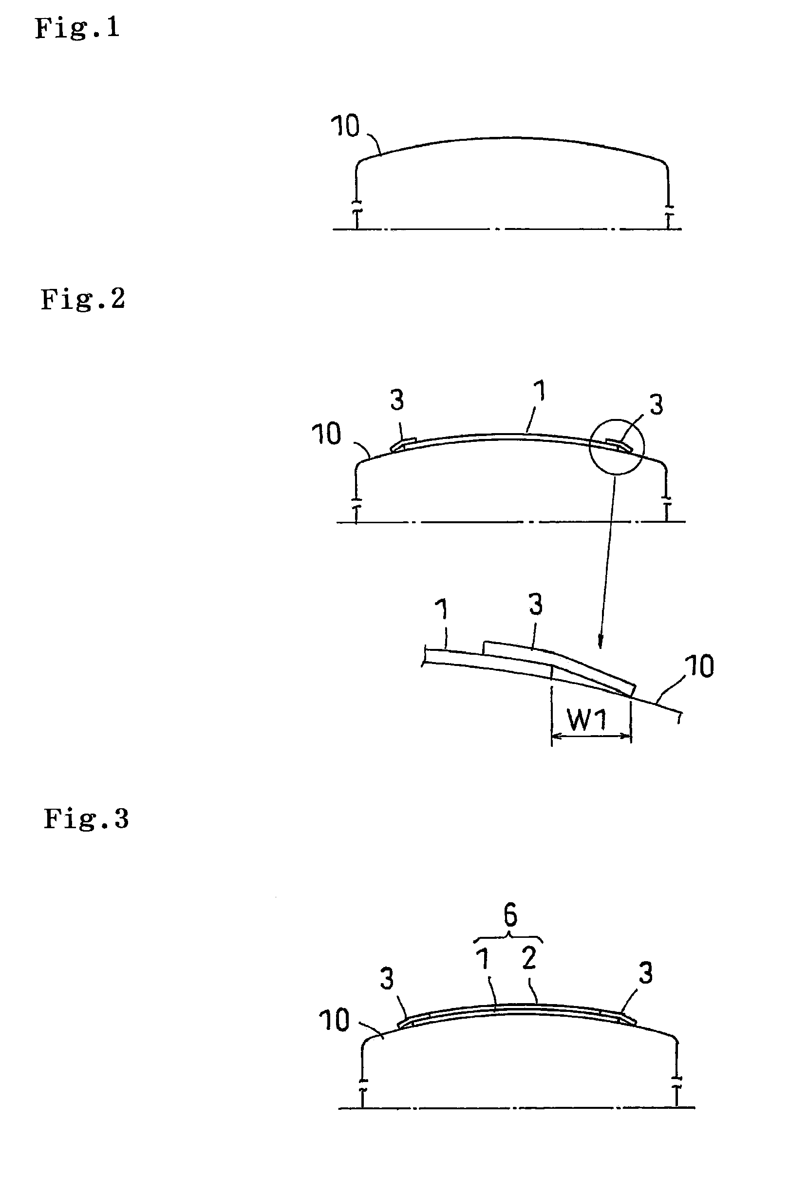
[0026]An embodiment of the present invention will be explained with reference to the drawings. FIG. 1 is a vertical cross sectional view of a belt drum used in the present embodiment.

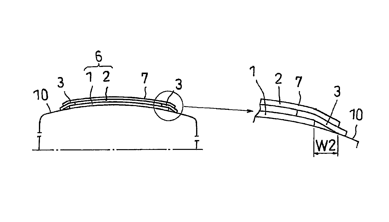
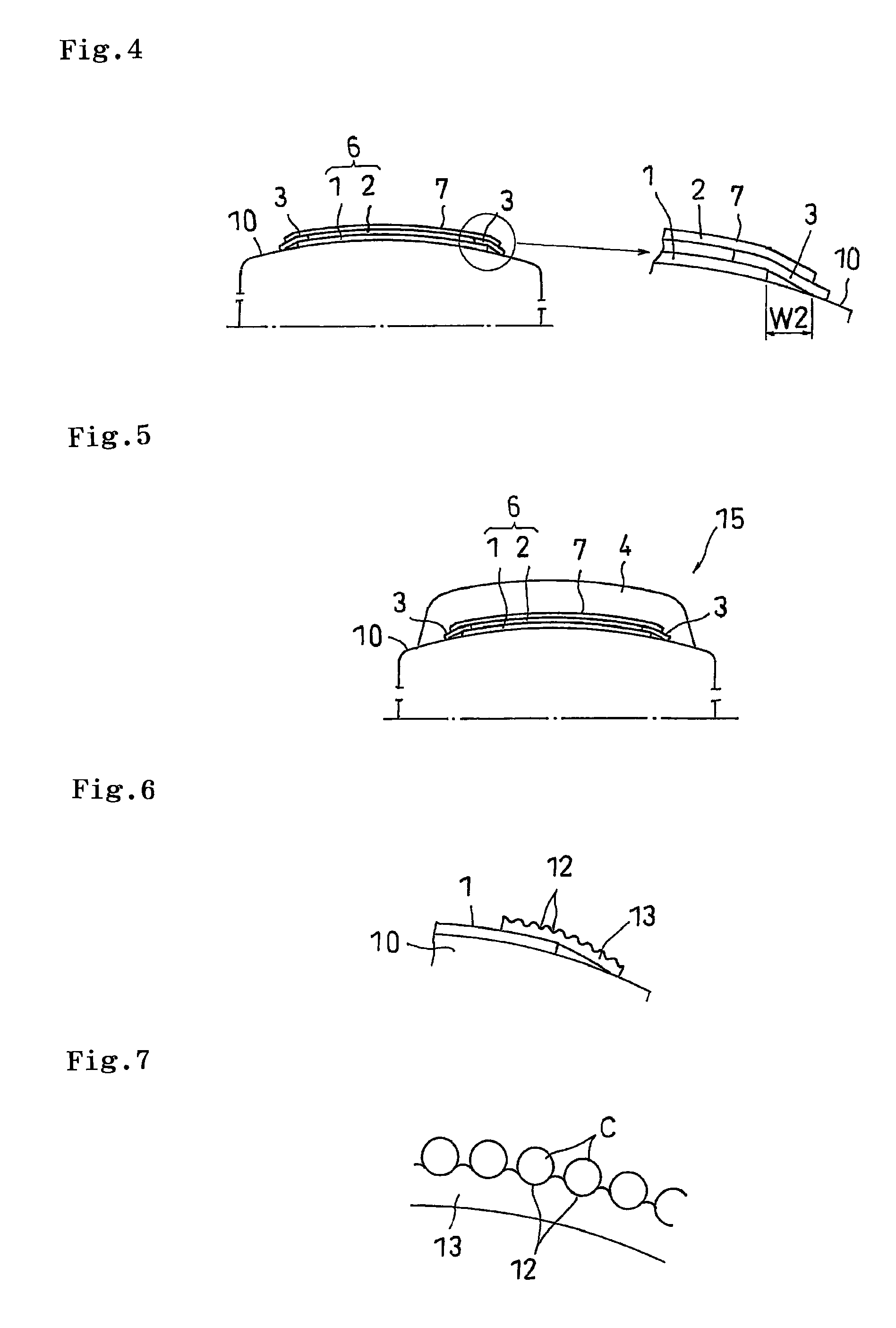
[0027]A belt drum 10 is structured such as to be diametrically expandable and compressible, and an outer peripheral cross sectional shape along an axial direction is formed as a circular arc shape protruding to an outer side in a diametrical direction, at least in a diametrically expanded state shown in FIG. 1. An outer peripheral surface of the belt drum 10 has one radius of curvature or a plurality of radii of curvature, and has a curvature which is close to a curvature of a belt layer of a product tire after a vulcanization forming. In the belt drum 10, a belt and tread assembly is formed. A step of forming the belt and tread assembly has a first step of laminating a plurality of belt plies so as to form a belt layer, and a second step of forming a belt reinforcing layer in an outer periphery of the ...


PUM

PropertyMeasurementUnit
angleaaaaaaaaaa
angleaaaaaaaaaa
widthaaaaaaaaaa

Abstract

First, a first belt ply is wound around an outer peripheral surface of a belt drum having a curvature so as to be formed as a tubular shape, and a rubber layer protruding to an outer side than an end portion in a width direction of a belt reinforcing layer is arranged in an outer periphery of an end portion in a width direction of the first belt ply. Further, a second belt ply which is narrower than the first belt ply is wound around an outer periphery of the second belt ply so as to be formed as a tubular shape, and a belt layer is formed in such a manner that the first belt ply and the second belt ply are laminated. The belt reinforcing layer is formed by spirally winding a rubber-coated reinforcing cord around an outer peripheral side of the formed belt layer, and an end portion in a width direction of the belt reinforcing layer is arranged in an outer side than the first belt ply.

Description

BACKGROUND OF THE INVENTION[0001]1. Field of the Invention[0002]The present invention relates to a manufacturing method of a pneumatic tire, and more particularly to a manufacturing method of a pneumatic tire in which a belt reinforcing layer is constituted by a spiral belt.[0003]2. Description of the Related Art[0004]Conventionally, in a pneumatic tire, in order to reinforce a carcass with a so-called hoop effect, a belt layer and a belt reinforcing layer are arranged in an outer periphery of the carcass. Generally, the belt layer is formed by winding a first belt ply around an outer peripheral surface of a belt drum so as to be formed as a tubular shape, and thereafter winding a second belt ply around an outer periphery thereof so as to be formed as a tubular shape. The belt plies include cords which are inclined with respect to a tire circumferential direction, for example, at an angle between 10 and 40 degrees, and are laminated in such a manner that the cords intersect with eac...

Claims


Application Information

Patent Timeline
Patent Type & Authority Patents(United States)
IPC IPC(8): B29D30/30B29D30/42B60C9/18
CPCB29D30/1621B29D30/70B29D30/3021Y10T152/10765
Inventor UEDA, RYUICHI
Owner TOYO TIRE & RUBBER CO LTD
Why Eureka
Try Eureka