Electromagnetic actuator

a technology of electromagnetic actuators and actuators, applied in the direction of spray nozzles, basic electric elements, electrical appliances, etc., can solve the problems of affecting the electromagnetic efficiency, affecting the manufacturing process, and complicated implementation of such a known device, and achieve the effect of simple and elegant manner

Inactive Publication Date: 2006-11-16
ETO MAGNETIC GMBH
View PDF6 Cites 2 Cited by
  • Summary
  • Abstract
  • Description
  • Claims
  • Application Information

AI Technical Summary

Benefits of technology

[0014] One significant advantage of the present invention lies in the fact that, based on a non-specifically formed armature guide tube, adaptation to the circumferential geometry of a piston that is to be used can take place by means of suitable fine machining during the formation (e.g. engraving) of the protrusions according to the invention. This advantageously means that inexpensive mass-produced parts can be used as starting material for the armature guide tube, which merely have to be adapted to the armature by means of one further machining step, namely the formation of the protrusions, in the required precise machining operation.
[0015] As a result, a solution to the problem of precise and reliable guidance of an armature in an armature guide tube for electromagnetic actuators is combined with controlled air gap conditions and advantageous properties in respect of fluid flows in the armature guide tube in a surprisingly simple and elegant manner by virtue of the present invention.

Problems solved by technology

However, this may also be disadvantageous, depending on the specific use purpose.
While the described hydrodynamic properties can be controlled by such a procedure, and also the centering of the armature in the guide tube is improved, the implementation of such a known device is both complicated in manufacturing terms and may be problematic, for example from the point of view of mass production.
DE 102 18 445 itself even points to the problem of such a resulting, relatively large air gap (which thus adversely affects the electromagnetic efficiency).

Method used


Image

  • Electromagnetic actuator
  • Electromagnetic actuator

Examples


Embodiment Construction

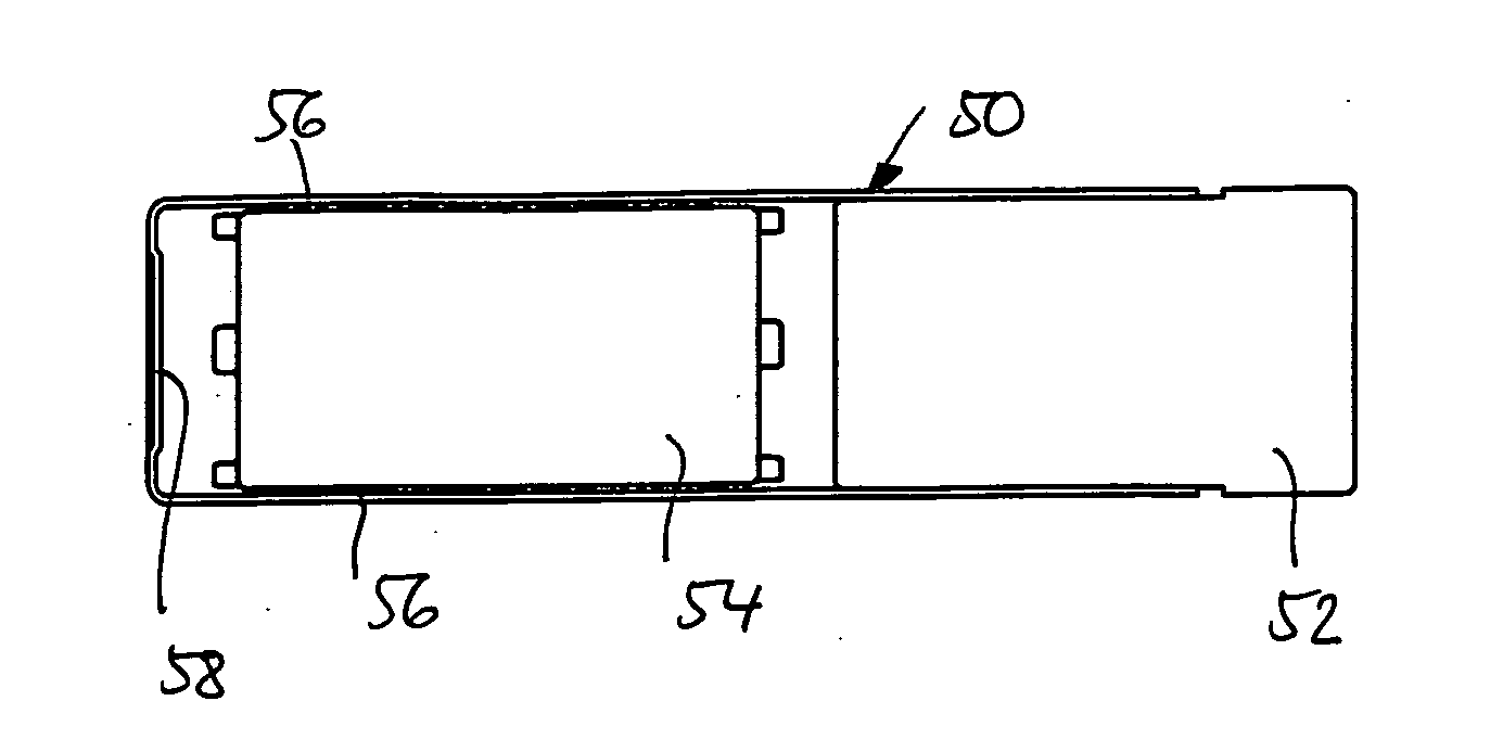
[0023] In respect of the structural formation of the peripheral equipment for the present invention, namely the manufacture of an electromagnetic actuator comprising a core held in a housing with an attached armature guide tube and the coil arrangement which surrounds the armature guide tube, reference is made for example to the generic document DE 102 35 644 A1 (for example FIG. 1 therein along with the associated description). However, as shown in FIGS. 1 to 5, the armature guide tube (which is referred to as the “magnet frame” in the prior art) is formed by a tubular or bushing-like element 50 which is made of magnetically nonconductive material and is produced by deep-drawing; FIG. 1 shows how this element is closed at one end by a core region 52, and an armature 54 is also shown in the sectional views of FIGS. 1, 2, said armature being kept centered in a central position by six protrusions 56 which are distributed radially around the circumference of the tube 50. In the illustr...


PUM


Abstract

An electromagnetic actuator comprising an armature (54) which is mounted in a sliding manner in a preferably hollow-cylindrical armature guide tube (50) and can be moved by means of an electric coil device, wherein, in order to form a sliding bearing for the armature, the armature guide tube has on the inside a plurality of protrusions (56) which are arranged around the circumference of the armature guide tube and are formed in one piece from the material of the armature guide tube.

Description

BACKGROUND OF THE INVENTION [0001] The present invention relates to an electromagnetic actuator. [0002] Such a device is known for example from German patent application 102 35 644 by the Applicant, wherein reference should be made for example to FIG. 1 of this publication to illustrate the background of the invention. [0003] An electromagnetic actuator of the generic type typically comprises a rotationally symmetrical magnet frame which is held in a housing and forms a guide tube for an armature element. The guide tube is surrounded by a coil arrangement. [0004] As a reaction to the coil arrangement being actuated by an electrical signal, a force acts on the armature, as a result of which the latter is moved in the axial direction inside the armature guide tube (references 14, 16, 18 in FIG. 1 of DE 102 35 644). [0005] In creating such devices, which exist in numerous variants and are used for many purposes, the critical factor is the [lacuna] between the outer face of the armature...

Claims


Application Information

Patent Timeline
Patent Type & Authority Applications(United States)
IPC IPC(8): F02M51/00
CPCH01F7/1607
Inventor BECHLER, MATTHIASBITZER, JENS
Owner ETO MAGNETIC GMBH
Why Eureka
Try Eureka