Camshaft adjustment device

a technology of camshaft and adjustment device, which is applied in the direction of non-mechanical valves, engine components, valve details, etc., can solve the problems of large installation space and production-related difficulties, and achieve the effect of high operational safety, optimal switching and magnetic characteristics, and simple and elegant manner

Active Publication Date: 2015-01-27
ETO MAGNETIC GMBH
View PDF14 Cites 1 Cited by
  • Summary
  • Abstract
  • Description
  • Claims
  • Application Information

AI Technical Summary

Benefits of technology

[0020]Within the scope of a preferred embodiment it has proved to be favourable that the drive units are assigned a common housing, which particularly preferably interacts on the face end with a housing guide portion which typically offers guides—typically in the form of through-openings running parallel to one another, in particular through-bores—for the plurality of tappet units, wherein these must then be arranged relative to one another and with respect to the camshaft axis of rotation so that at least one tappet longitudinal centre axis does not intersect the aforementioned axis of rotation. The result created by the present invention in a surprisingly simple and elegant manner is an arrangement which combines a compact design with assembly-friendliness, high operational safety and optimal switching and magnetic characteristics while ensuring generous overlap regions between the tappet units and the drive units at the same time.

Problems solved by technology

This results in a comparatively large installation space that is required.
Disadvantageous are also production-related difficulties.

Method used


Image

  • Camshaft adjustment device
  • Camshaft adjustment device
  • Camshaft adjustment device

Examples


Embodiment Construction

[0027]The figures of the same element and elements having the same functions are marked with the same reference characters.

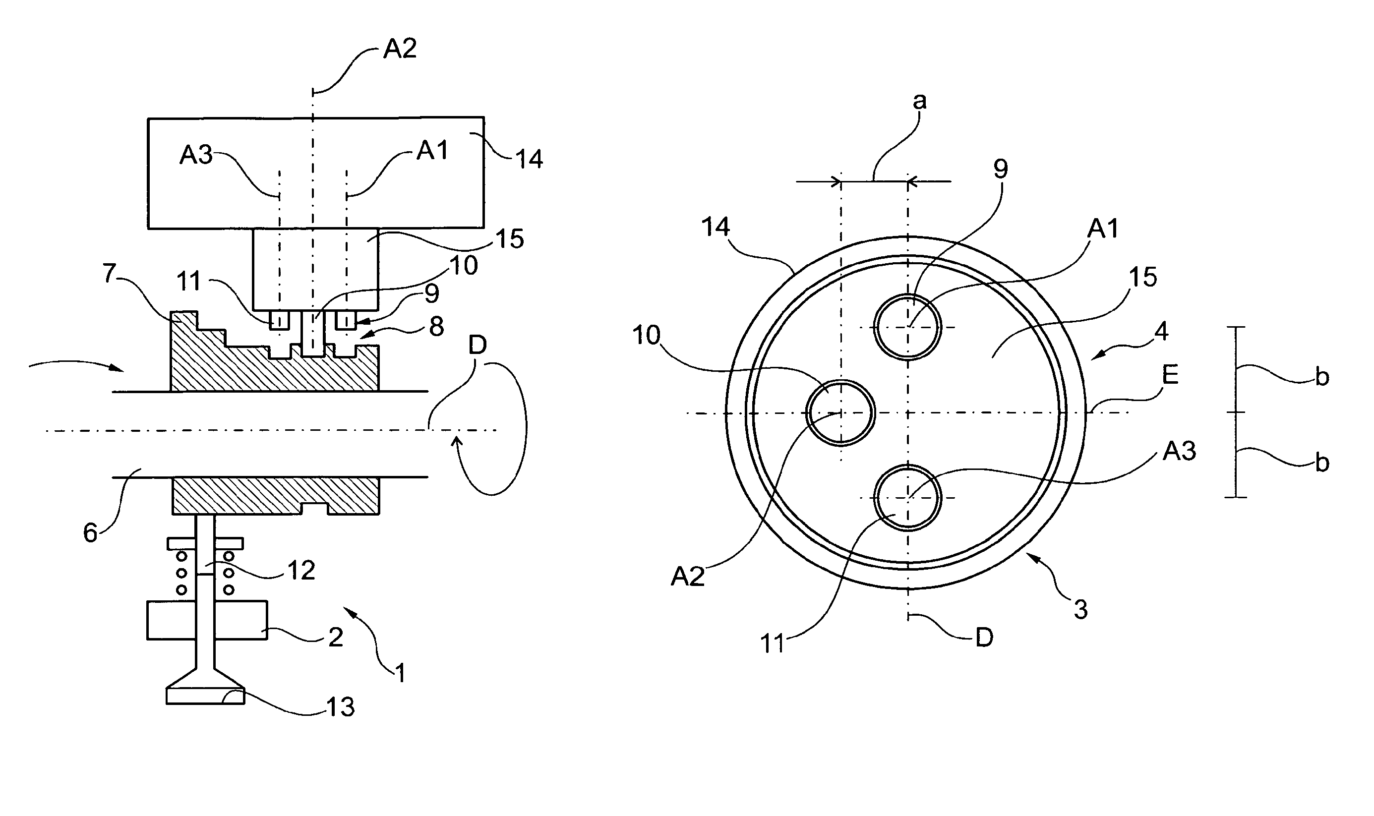
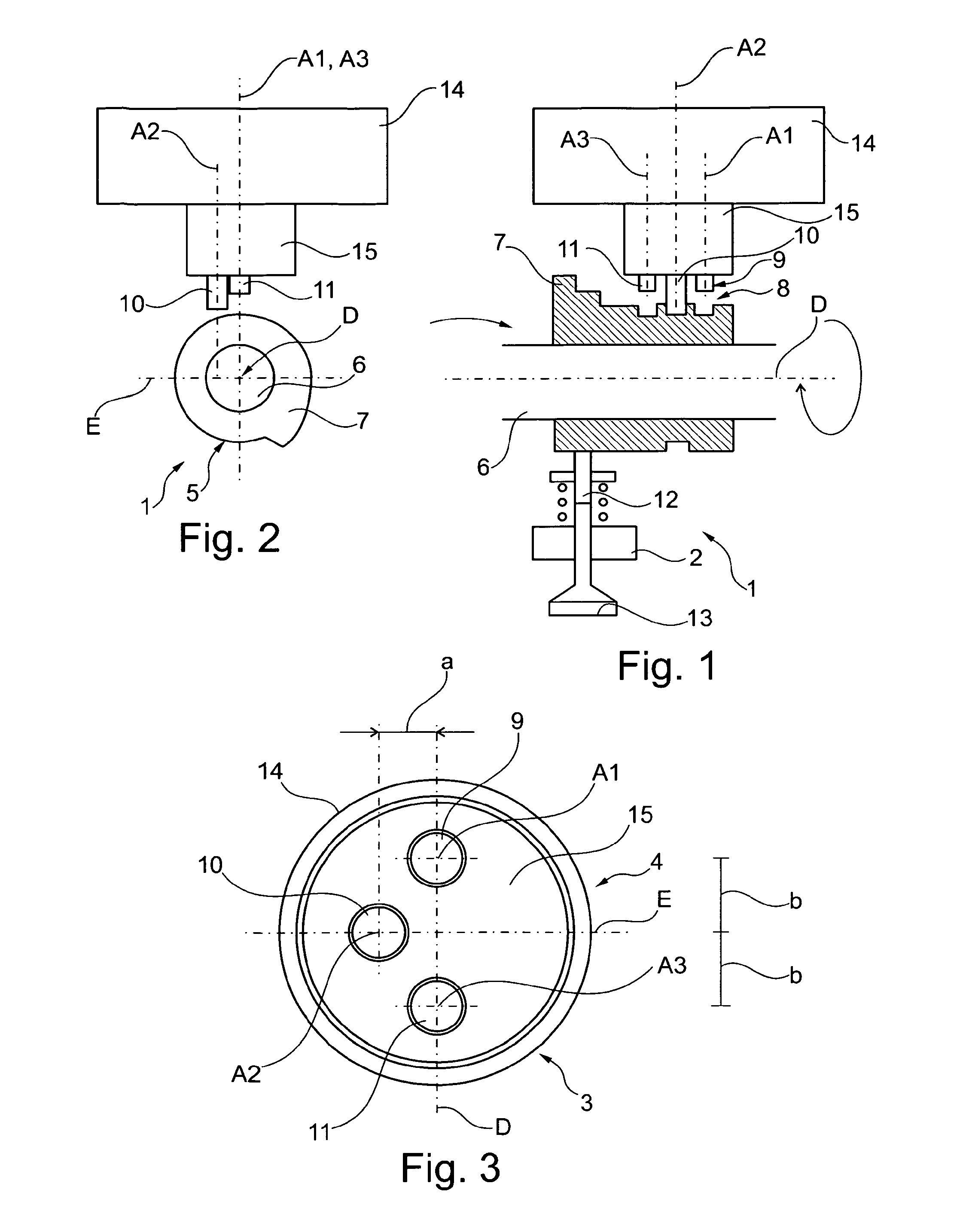
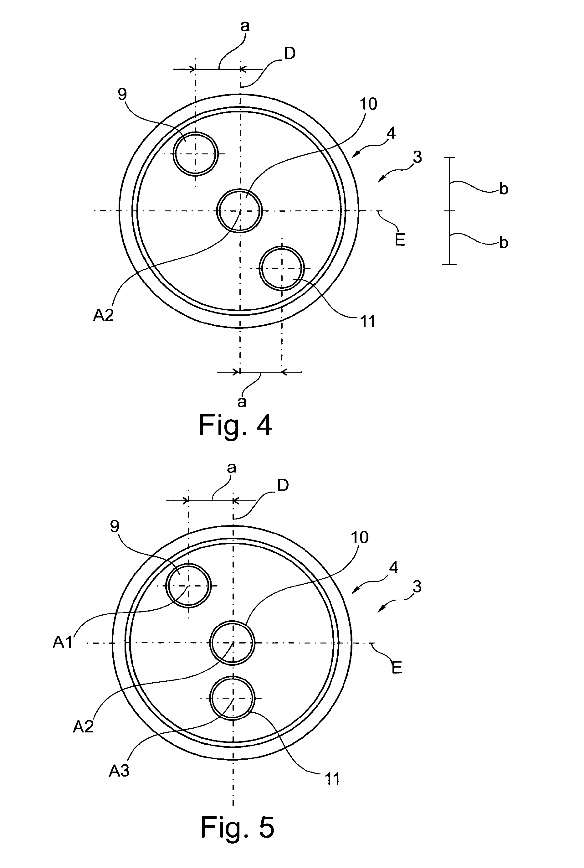
[0028]FIGS. 1 and 2 show exemplary embodiments of variable gas exchange valve drives for an internal combustion engine 2 indicated in FIG. 1. FIGS. 1 and 2 in this case show possible configurations of the camshaft adjusters 3 with an electromagnetic multi-tappet actuating device 4. The camshaft adjusters 3 according to FIGS. 1 and 2 each comprise a camshaft 5, comprising a carrier shaft 6 on which a cam piece 7 with a plurality of cam elevations of different geometry is arranged in a rotationally fixed and axially displaceable manner. The carrier shaft 6 is rotatorically driveable about a camshaft axis of rotation D by means of the internal combustion engine 2. In the cam piece 7, spirally formed shifting grooves 8 are introduced adjacently to the cam elevations, wherein the shifting grooves 8 are assigned a plurality of, in the shown exemplary embodiment, three...


PUM


Abstract

A camshaft adjuster (3), comprising a camshaft axis of rotation (D) and an electromagnetic multi-tappet actuating device (4) having at least two electromagnetic drive units, which for exerting an actuating force on a corresponding number of elongated tappet units (9, 10, 11) which are mounted axially parallel to one another, each defining a tappet longitudinal center axis (A1, A2, A3) arranged perpendicularly to the camshaft axis of rotation (D) are activatable, in order to engage with the tappet units (9, 10, 11) in shifting grooves (8) of an adjustable cam piece (7), wherein the drive units each on a facing acting end on one of the associated tappet units (9, 10, 11) form an acting surface that is moveable in an actuating direction of the drive units and an end face on the acting side facing away from the respective associated shifting groove (8) of a respective one of the tappet units (9, 10, 11) interacts with the acting surface, wherein at least one of the tappet units (9, 10, 11) is arranged relative to the camshaft axis of rotation (D) in such a manner that its tappet longitudinal center axis (A1, A2, A3) running parallel to the tappet longitudinal center axes (A1, A2, A3) of the at least one other tappet unit (9, 10, 11) is spaced from the camshaft axis of rotation (D) in a plane (E) receiving the camshaft axis of rotation (D) and running perpendicularly to the tappet longitudinal center axes (A1, A2, A3).

Description

BACKGROUND OF THE INVENTION[0001]The present invention relates to a camshaft adjuster according to the preamble of Patent Claim 1, comprising a camshaft axis of rotation defined by a camshaft, in particular by a carrier shaft of a camshaft, about which the camshaft is rotatable.[0002]Because of the limited installation space in the region of a displacement engine of a motor vehicle there is frequently the need of realising the electromagnetic multi-tappet actuating device, comprising a plurality of activatable (typically selectively, i.e. independently of one another) tappet units in a sufficiently compact manner, so that on the one hand a sufficient electromagnetic functionality is ensured (for example with respect to the necessary adjusting stroke of the tappet units as well as reaction or switching times) and on the other hand there is no undesirable mutual influencing—mechanically or electromagnetically.[0003]From DE 10 2007 040 677 A1 a camshaft adjuster is known, in which the ...

Claims


Application Information

Patent Timeline
Patent Type & Authority Patents(United States)
IPC IPC(8): F01L1/14F01L1/344F01L13/00
CPCF01L1/344F01L13/0036F01L2013/0052F01L2013/101
Inventor WERNER, MATTHIASGOLZ, THOMAS
Owner ETO MAGNETIC GMBH
Why Eureka
Try Eureka