
Electromagnetic valve device, use thereof, and system

a technology of electromagnetic valve and valve body, applied in the direction of lift valve, valve details, brake systems, etc., can solve problems such as increasing problems, and achieve the effect of reducing complexity, simple and elegant manner

Active Publication Date: 2019-01-31
ETO MAGNETIC GMBH
View PDF1 Cites 0 Cited by
  • Summary
  • Abstract
  • Description
  • Claims
  • Application Information

AI Technical Summary

Benefits of technology

The invention is a valve device that is flexible and easy to adjust for different conditions. It is designed to be a compact, efficient, and easily switched multi-arrangement of valves. The valve casing is easily mounted using a plastic injection molding technology that allows for large-scale production and minimizes assembly space. The invention simplifies the manufacturing process and reduces assembly space requirements for pilot-controlled valves, especially for NO andNC technologies. Overall, the invention offers a simplified and flexible solution for valve devices.

Problems solved by technology

This problem becomes more acute by the circumstance that—depending on the presetting of the motor vehicle producer—standardized fastening and mounting conditions typically prevailing at an assembly site, which purport as well as necessitate a required outer design of the valve device and this, moreover, in an environment normally with a lack of space.

Method used


Image

  • Electromagnetic valve device, use thereof, and system
  • Electromagnetic valve device, use thereof, and system
  • Electromagnetic valve device, use thereof, and system

Examples


Embodiment Construction

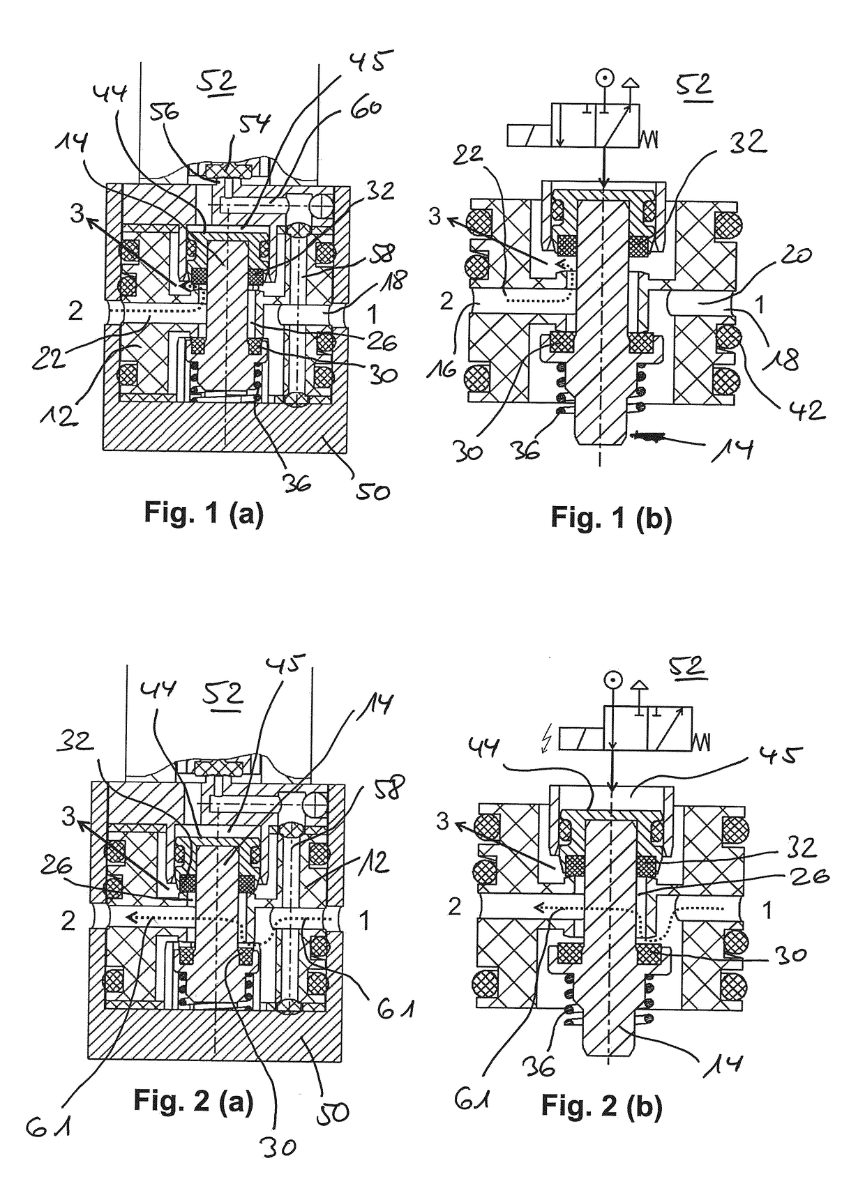
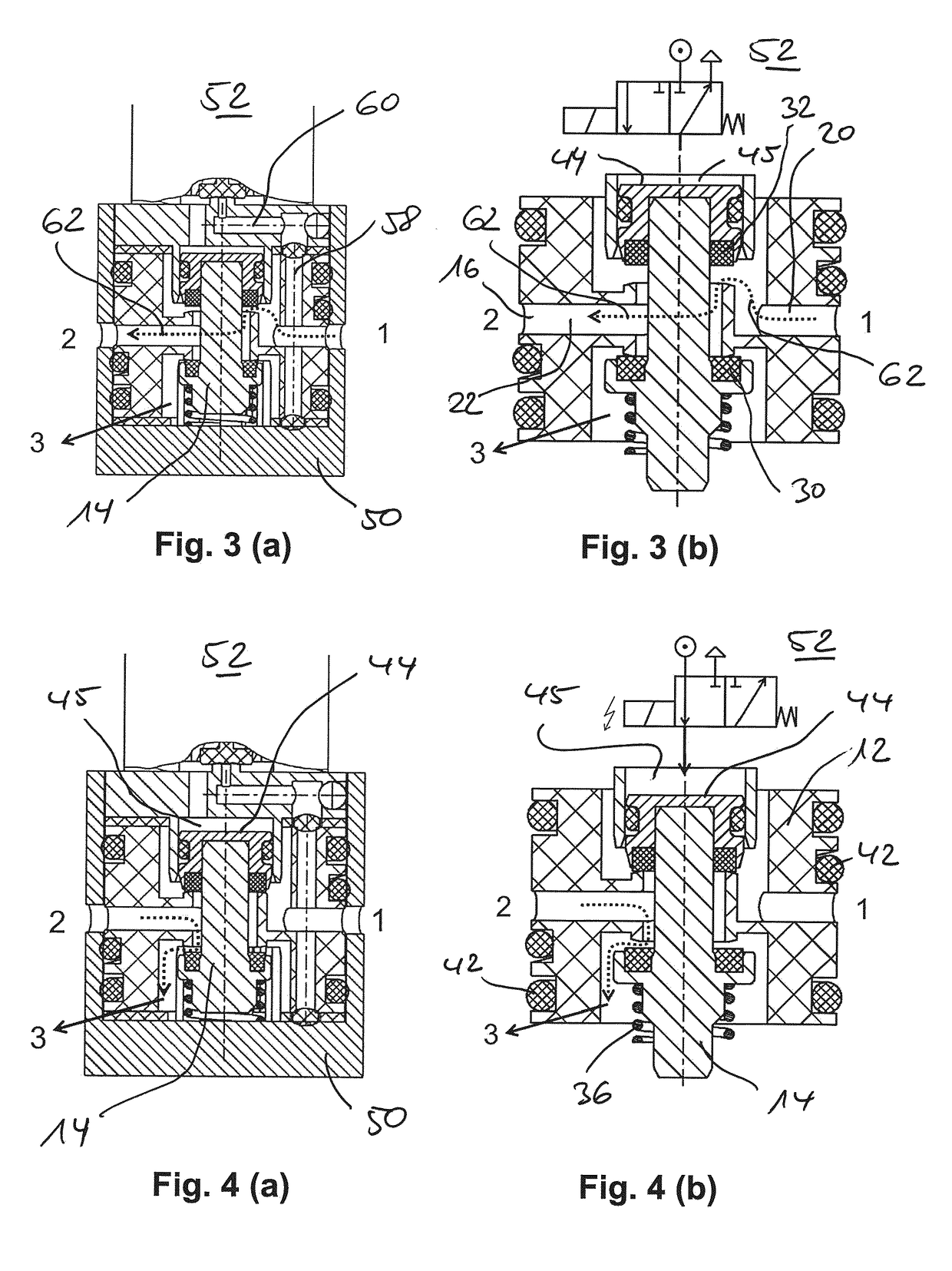
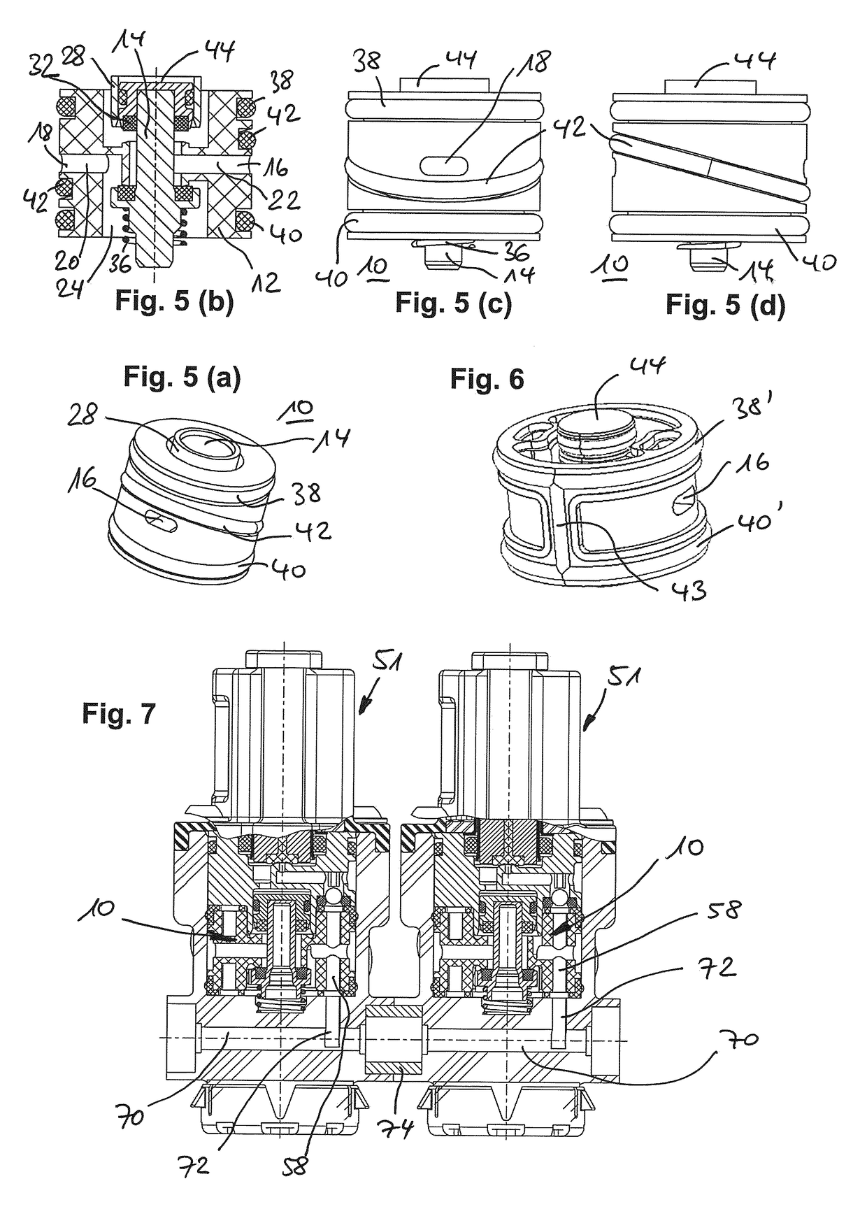
[0028]More explicitly, this valve casing 10 is essentially made of a plastic body 12, which is made of a hard plastic material via an injection molding process and on the one hand provides a guide for an axial pestle unit 14 movably axially mounted in the interior and on the other hand comprises a channel and fluid guiding infrastructure, which, on a jacket side, forms a first opening 16 and a second opening 18, which is formed on an opposite side of the jacket side, each opening 16 and 18 having connecting fluid guiding channels 20, 22 initially extending radially. These open into a central opening 24 on the bottom side in the instance of channel 22, and in the form of middle slots or rather valve-seat-like outlets 26 parallel to the axis in the instance of channel 22, said outlets 26 being open in both axial directions and surrounding the pestle unit 14 or rather extending around the jacket.[0029]As in particular the longitudinal section views in FIG. 5(b) illustrates in this rega...


PUM


Abstract

An electromagnetic valve device having a fluid inlet port (1), which is formed in a valve casing (10), for a fluid to be switched, in particular pneumatic fluid, a working port (2), which is realized in the valve casing, for the fluid and locking component(s) (14), which are moveably guided in the valve casing along an axial direction and which are realized for interacting with a valve seat (26) formed in the valve casing and opening a fluid flow path between the fluid inlet port and the working port and which are moveably realized via fluid switched by means of electromagnetic positioning means (32).

Description

BACKGROUND OF THE INVENTION[0001]The invention relates to an electromagnetic valve device according to the preamble of the independent claim. Furthermore, the invention at hand relates to a usage of such an electromagnetic valve device, and the invention at hand relates to a system comprising at least two of the generic electromagnetic valve devices.[0002]From the state of the art, generic valve devices in the form of so-called pilot-controlled electromagnetic valves are generally known. In this embodiment of an electromagnetic valve also known as “booster technology”, an armature, which is movable in an otherwise known manner in electromagnetic positioning means in response to stationary spool means being energized, interacts indirectly with a valve seat for opening or closing a fluid flow path; a fluid flow then would generally be released or blocked from the fluid inlet port (also referred to as a “pressure port”) to the working port by means of the valve seat. Indeed, the electr...

Claims


Application Information

Patent Timeline
Patent Type & Authority Applications(United States)
IPC IPC(8): F16K11/048B60T15/02B60T8/36F16K27/02F16K31/42
CPCF16K11/048B60T15/027B60T8/361B60T8/3675F16K27/0263F16K27/0281F16K31/423B60T8/362F15B2013/006F16K1/44
Inventor THODE, OLIVERRAFF, VIKTOR
Owner ETO MAGNETIC GMBH
Learn More