Rotary dispenser for multiple cartridge

a technology of multiple cartridges and dispensers, which is applied in the direction of liquid surface applicators, coatings, etc., can solve the problems of dispensers that are not functional, dispensers that are additionally only suitable for discharging, and threaded spindles being pressed, etc., and achieves the effect of simple design and reliable operation

Inactive Publication Date: 2017-08-10
MEDMIX SYST
View PDF58 Cites 1 Cited by
  • Summary
  • Abstract
  • Description
  • Claims
  • Application Information

AI Technical Summary

Benefits of technology

[0005]It is an object of the present invention to provide a discharge device which is suitable for simultaneously discharging two or more components from a multiple cartridge or from separate syringes, said device being simple in design and functioning reliably even when used at a high discharge pressure.

Problems solved by technology

In this case, storing two or more components of such a product in separate syringes or in separate chambers of a multiple cartridge and not mixing them to form the finished product until they are discharged is known, as the finished product is not suitable for storage in the mixed state.
The container is additionally only suitable for discharging one single component or one single finished product.
In particular, where there is high counter pressure, there is the risk here of the threaded spindle being pressed out of the guide bush in the proximal direction, as a result of which the dispenser would be non-functional.
In addition, said dispenser is only suitable for single use and, in particular, is not able to be used with replacement containers.

Method used


Image

  • Rotary dispenser for multiple cartridge
  • Rotary dispenser for multiple cartridge
  • Rotary dispenser for multiple cartridge

Examples


Embodiment Construction

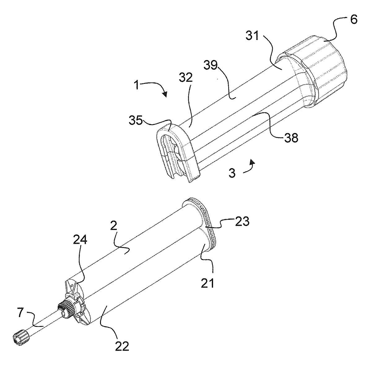
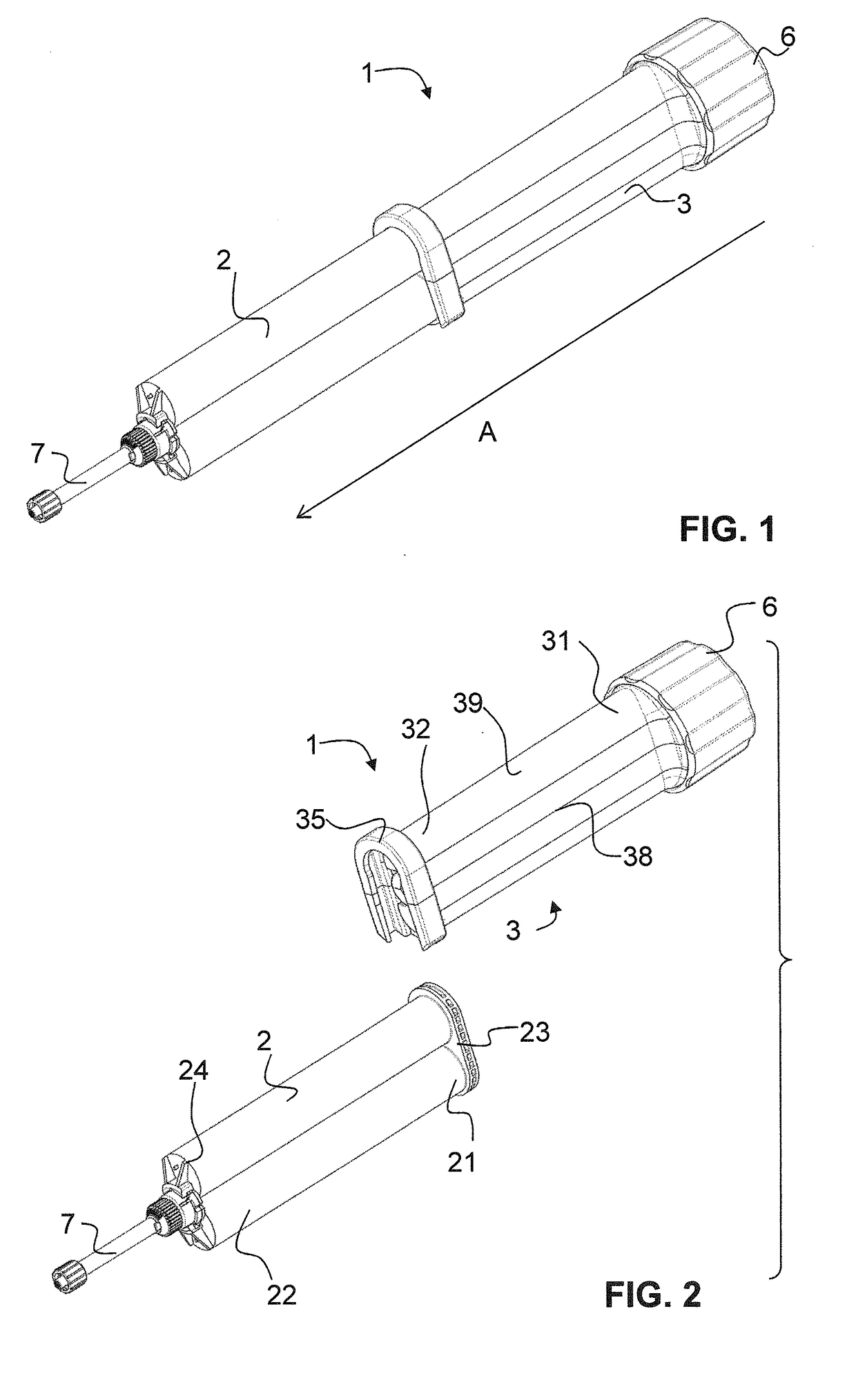
[0034]FIGS. 1 to 13 illustrate different views of a preferred embodiment of a discharge device 1 according to the invention. A double cartridge 2, which is provided with a mixing attachment 7, can be fastened to the discharge device.

[0035]A distal direction A is defined as the direction along which the pistons of the double cartridge move in order to discharge components from the double cartridge 2 into the mixing attachment 7. The opposite direction to this is designated as the proximal direction. Both the distal and the proximal direction can be designated as the axial direction. Any direction which runs transversely to the axial direction is designated as the lateral or sideways direction.

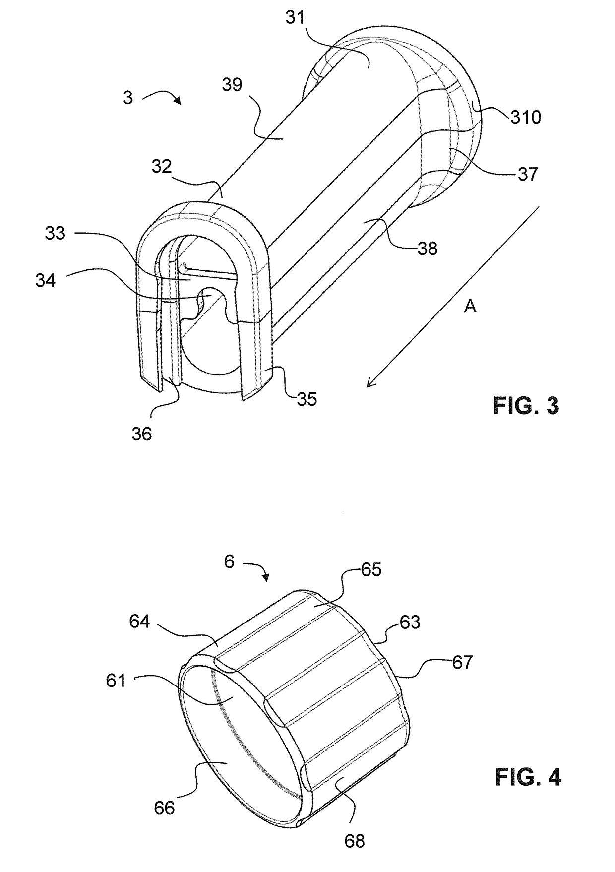
[0036]As can be seen in particular from FIGS. 7 and 11, the discharge device 1 comprises a housing 3, a threaded rod 4, an advancing element in the form of a double plunger 5 and a rotary member in the form of a rotary drum 6. The housing 3 is shown on its own in FIG. 3; the threaded rod is show...


PUM


Abstract

A discharge device that serves the purpose of discharging at least two components from a multiple cartridge. The discharge device has a housing, a threaded rod and an advancing element with an internal thread. The threaded rod engages in the internal thread of the advancing element such that the advancing element can be pushed forward in a distal direction by turning the threaded rod in relation to the housing. In the region of its distal end, the threaded rod has a taper. Formed on the housing, in the region of its distal end, is a holding element. The holding element has a laterally open clearance, and the threaded rod is pushed with its taper laterally into the clearance of the holding element such that the holding element fixes the threaded rod axially in the housing in the distal direction and in a proximal direction opposite thereto.

Description

TECHNICAL FIELD[0001]The present invention relates to a discharge device for a multiple cartridge or for at least two syringes in order to discharge at least two components from the multiple cartridge or from the syringes. Such a discharge device is also designated below as a dispenser.PRIOR ART[0002]In various technical areas discharge devices are used to discharge a flowable (fluid) product, thus for example, in the fields of medical or dental technology. In this case, storing two or more components of such a product in separate syringes or in separate chambers of a multiple cartridge and not mixing them to form the finished product until they are discharged is known, as the finished product is not suitable for storage in the mixed state. Examples are medical and non-medical two-component adhesives, bone cement, etc. Discharge devices which are suitable for discharging and mixing two separately stored components are disclosed, for example, in the documents WO 2007 / 041266, WO 2009 / ...

Claims


Application Information

Patent Timeline
Patent Type & Authority Applications(United States)
IPC IPC(8): B05C17/005B05C17/01
CPCB05C17/01B05C17/00553B05C17/0133
Inventor FURRER, MANUELMATHYS, BEAT
Owner MEDMIX SYST
Why Eureka
Try Eureka