Optical ground tracking apparatus, systems, and methods

a technology of optical ground tracking and equipment, applied in the field of optical ground tracking equipment, systems and methods, can solve the problems of affecting the comfort and convenience of residents, and bringing huge financial costs to businesses

Active Publication Date: 2017-12-12
SEESCAN
View PDF25 Cites 29 Cited by
  • Summary
  • Abstract
  • Description
  • Claims
  • Application Information

AI Technical Summary

Problems solved by technology

The unintended destruction of power and data cables may seriously disrupt the comfort and convenience of residents and bring huge financial costs to businesses.

Method used


Image

  • Optical ground tracking apparatus, systems, and methods
  • Optical ground tracking apparatus, systems, and methods
  • Optical ground tracking apparatus, systems, and methods

Examples


example embodiments

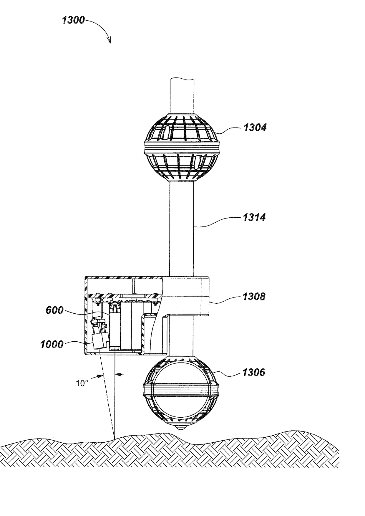
[0072]According to one aspect of the present disclosure, a locator may be configured to detect the variable reflectivity or coloration of ground or other surfaces or terrains, including markings laid on the ground and / or occasional encountered objects lying on the ground. To accomplish this, an LED light source, which may be highly directional, may be optionally combined with a near-range color sensor array.

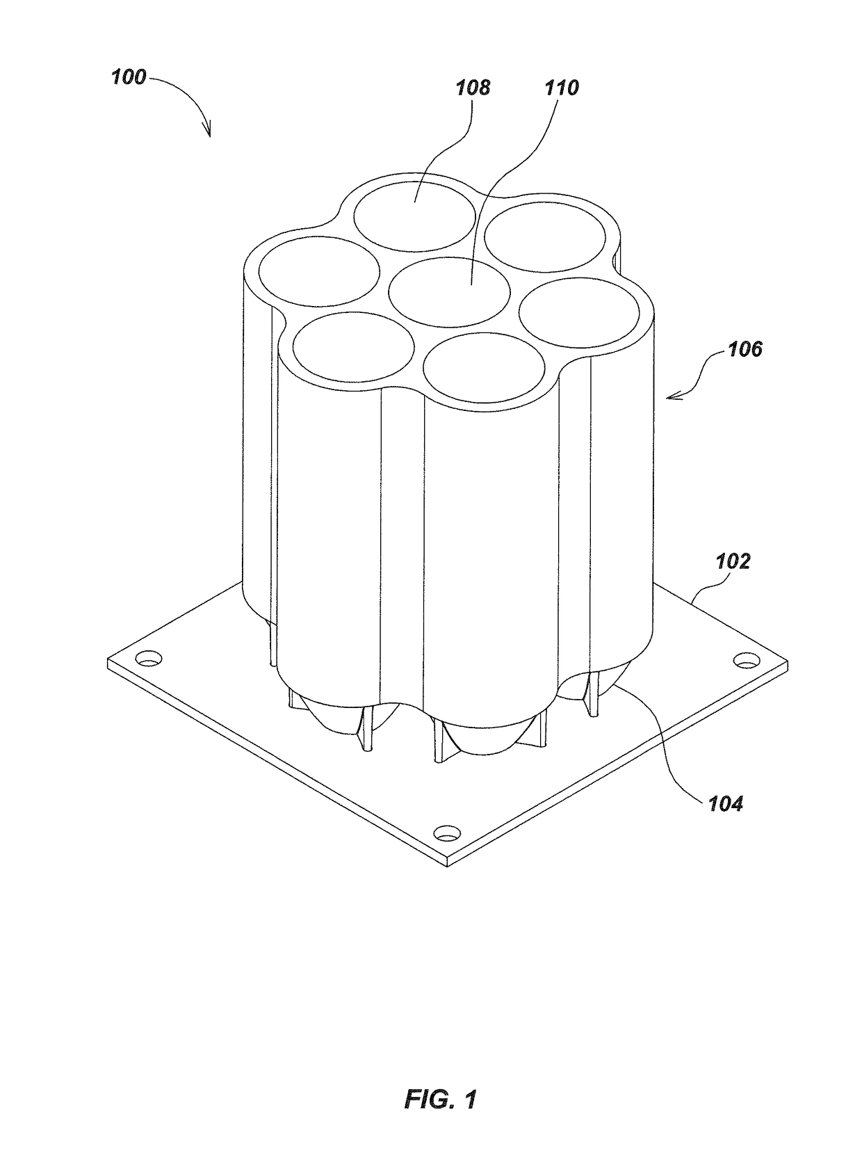
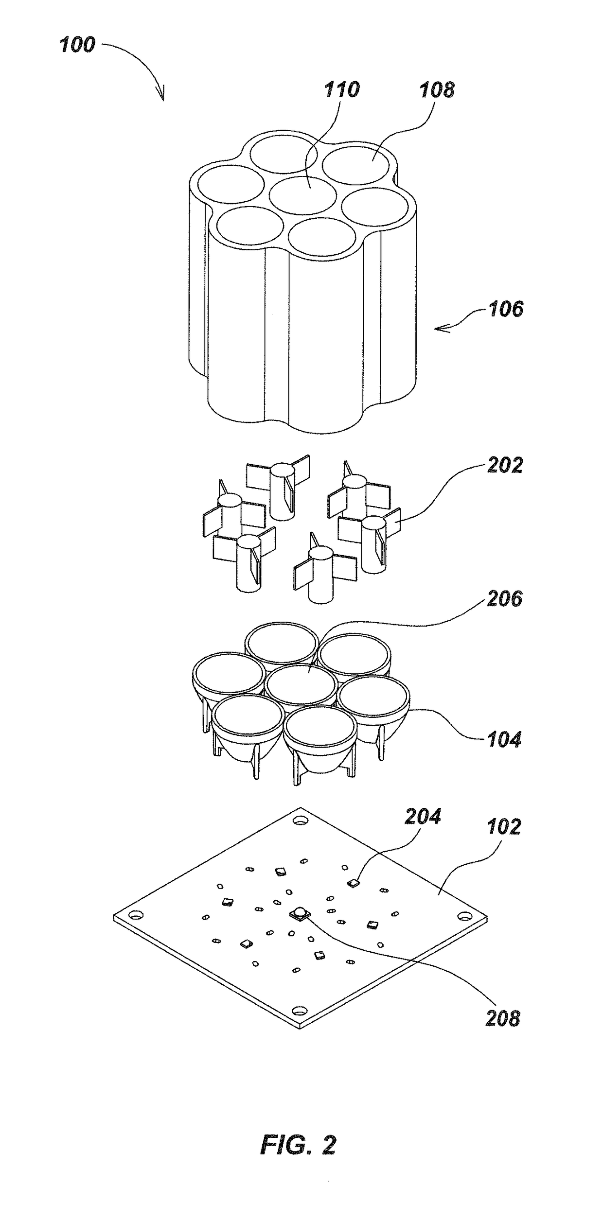
[0073]In one aspect, a formed snoot may be coupled with a color sensor array in order to improve the directionality of returned light to the sensor array. The snoot may be a single formed set comprising multiple light-guiding tubes, for example. Alternatively, tubular snoots may be fabricated individually and bundled together in the assembly process or otherwise combined.

[0074]Referring to FIG. 1, an embodiment of a color sensing assembly 100 in accordance with certain aspects is illustrated. The color sensing assembly 100 may include a circuit board, such as printed circuit boar...


PUM

PropertyMeasurementUnit
angleaaaaaaaaaa
angleaaaaaaaaaa
magnetic fieldsaaaaaaaaaa

Abstract

Optical ground tracking apparatus for use with buried object locators or other instruments or devices are disclosed. In one embodiment, a buried object locator includes a locator module disposed in our coupled to the housing to sense a buried object based on emitted magnetic fields, and a surface tracking module for determining motion information of the buried object locator based on light reflected from a tracking surface.

Description

CROSS-REFERENCE TO RELATED APPLICATIONS[0001]This application is a continuation of and claims priority to co-pending U.S. Utility patent application Ser. No. 13 / 766,670, filed on Feb. 13, 2013, entitled OPTICAL GROUND TRACKING APPARATUS, SYSTEMS, AND METHODS, which claims priority under 35 U.S.C. §119(e) to U.S. Provisional Patent Application Ser. No. 61 / 598,312, filed on Feb. 13, 2012, entitled OPTICAL GROUND TRACKING LOCATOR DEVICES AND METHODS, to U.S. Provisional Patent Application Ser. No. 61 / 615,810, filed on Mar. 26, 2012, entitled GROUND-TRACKING SYSTEMS AND APPARATUS, to U.S. Provisional Patent Application Ser. No. 61 / 618,746, filed on Mar. 31, 2012, entitled DUAL ANTENNA SYSTEMS WITH VARIABLE POLARIZATION, and to U.S. Provisional Patent Application Ser. No. 61 / 679,672, filed Aug. 3, 2012, entitled OPTICAL GROUND TRACKING APPARATUS, SYSTEMS & METHODS. The contents of each of these applications are incorporated by reference herein in their entirety for all purposes. These ap...

Claims


Application Information

Patent Timeline
Patent Type & Authority Patents(United States)
IPC IPC(8): G01N21/00G01S17/02G01S17/06G01S17/08G01S17/88G01S17/89G01B11/14G01V11/00G01C3/08G01S3/786G01V3/08G01J3/46G01V3/15G01V3/10G01S17/86
CPCG01S17/023G01B11/14G01C3/08G01J3/46G01S3/786G01S17/06G01S17/88G01S17/89G01V3/081G01V3/15G01V11/00G01S17/08G01V3/10G01J2003/467G01J3/0202G01J3/021G01J3/0262G01J3/50G01J3/0291G01S17/86
Inventor OLSSON, MARK S.CHAPMAN, ERIC M.MEREWETHER, RAYALDRIDGE, SEQUOYAH
Owner SEESCAN
Why Eureka
Try Eureka