
Heat exchange system for casings of rotary electric machines

a technology of heat exchange system and rotating electrical machine, which is applied in the direction of heat exchange apparatus, dynamo-electric machines, supports/encloses/casings, etc., can solve the problems of difficult homogeneous application of paint, construction of structures finned in labyrinth or segregation, and reasonable constructive complexity. , to achieve the effect of free of cost to the manufacturing process

Active Publication Date: 2017-12-12
WEG EQUIP ELETRICOS SA
View PDF15 Cites 1 Cited by
  • Summary
  • Abstract
  • Description
  • Claims
  • Application Information

AI Technical Summary

Benefits of technology

[0009]This invention aims at overcoming the disadvantages of the state of the art, disclosing an alternative purpose of the rotating electrical machine casing, equipped with modified geometry fins, interleaved with the neighbor fins, in the front longitudinal region, in which the heat exchange area increment occurs, free of cost to the manufacturing process.

Problems solved by technology

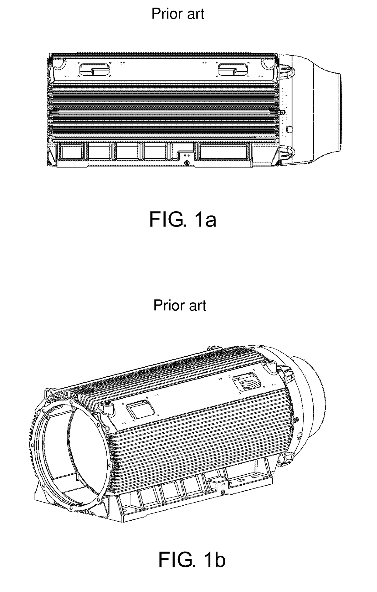
It is noted from the background that the common projects show a reasonable constructive complexity affecting in the manufacturing costs, besides difficulting the product finishing final steps, such as the process to eliminate the burrs in the casted part and the painting.
In the documents previously mentioned, it is possible to distinguish that the lack of spatial uniformity between the casing fins makes it difficult a homogeneous application of paint, besides demanding a greater attention in the quality control, in order to avoid irregularities, which may feature defects in the finishing.
The construction of structures finned in labyrinth or segregated constitutes a clear disadvantage regarding this factor, once additional care is needed when removing these edges of the finished product.

Method used


Image

  • Heat exchange system for casings of rotary electric machines
  • Heat exchange system for casings of rotary electric machines
  • Heat exchange system for casings of rotary electric machines

Examples


Embodiment Construction

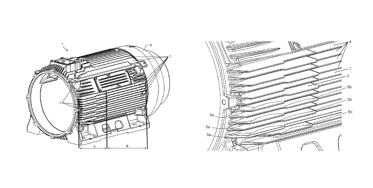
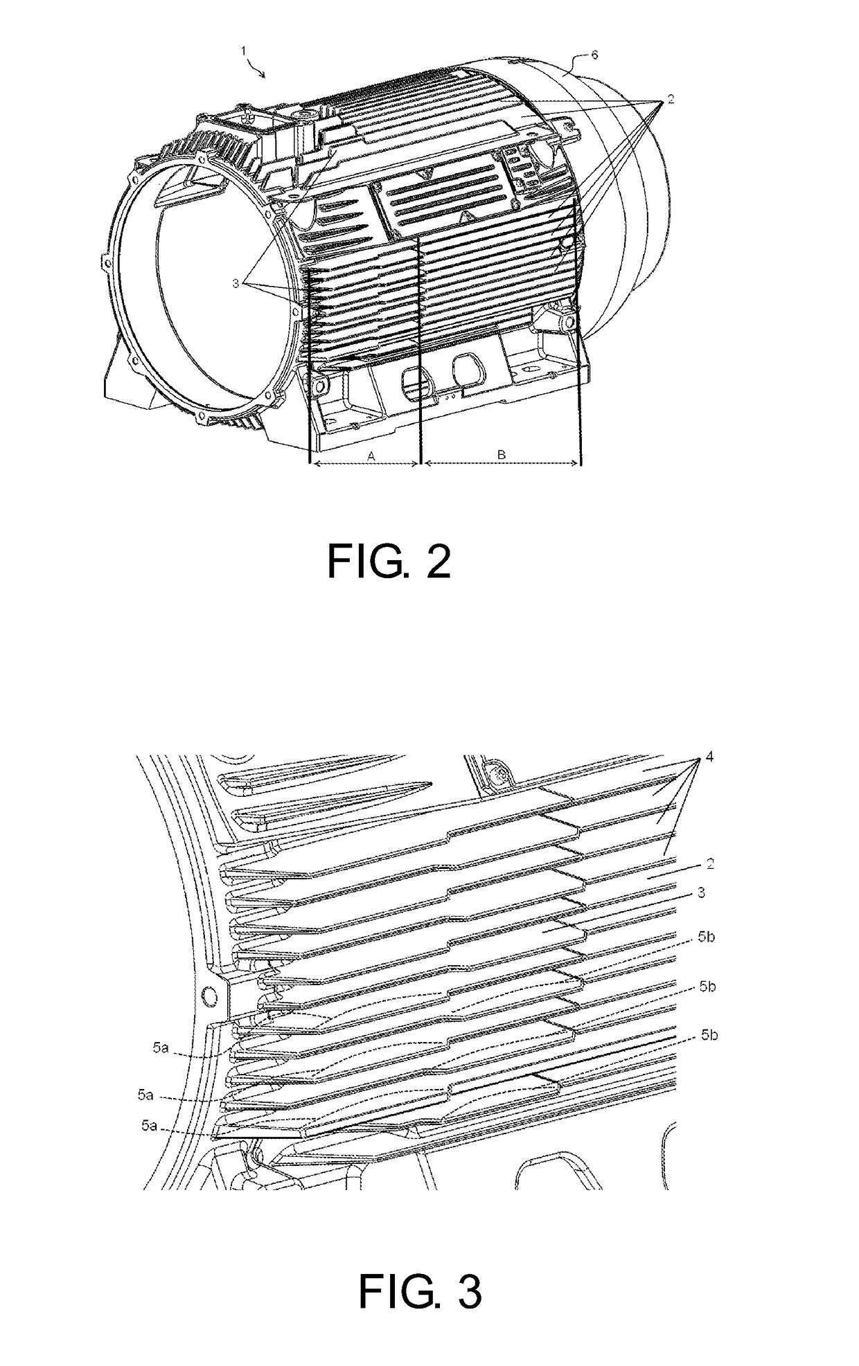
[0015]FIGS. 2 and 3 represent an embodiment of a rotating electrical machine comprising the proposed system. For reference purposes, the casing (1) is subdivided into a front portion (A) and a rear portion (B). It is adopted by convention that the (A) previous region is that in communication with the front lid (not showed in the figures) of a rotating electrical machine, while the (B) subsequent portion will correspond to the casing region proximal to the fan assembly (not showed in the figures) and the deflector lid (6).

[0016]FIG. 2 in a preferential embodiment illustrates an external view in the casing perspective (1), equipped with a number of fins (2) equipped with a modified and interleaved profile of the fin (3) in the front portion (A). The fins (2) and their modified and interleaved profile of the fin (3) in the front portion (A) are distributed over the side parts, in the upper and bottom parts of the external surface of the casing (1). The fins (2) and their modified and i...


PUM


Abstract

A heat exchange system for casings of rotary electric machines is described herein. The heat exchange system applied to the rotating electrical machine casing and the machine is equipped with a finned casing comprising a number of fins equipped with a modified profile, each one interleaved with complementary fins, both profiles distributed over the external surface of the casing. The fins have a predominantly continuous profile, supported in parallel along the casing height, and respectively show projections from a guideline, with structures with trapezoidal or rectangular section being interleaved to one another in a front region of the machine.

Description

APPLICATION FIELD[0001]This invention discloses a heat exchange system for rotating electrical machine casing comprising a singular distribution of fins in its front region, in a way to locally increment the convection coefficient and consequently increase the heat exchange without impacting the steps of casting and finishing of the finished product. In another aspect, the invention discloses a rotating electrical machine comprising the system now purposed.BACKGROUND OF THE INVENTION[0002]One of the factors that define the complexity degree of a finned casing of a rotating electrical machine is the height per distance ratio between the fins; such ratio affects the casting process and the finishing process of the finished product, especially in painting. An optimization of the fins aiming at maximizing the convection coefficient may result in a minimization of this ratio without compromising the heat exchange in most part of the casing surface. However, it is unavoidable that along t...

Claims


Application Information

Patent Timeline
Patent Type & Authority Patents(United States)
IPC IPC(8): H02K5/18F28F13/06H02K15/02F28F3/02
CPCH02K5/18F28F3/02H02K15/02F28F13/06F28F2215/04
Inventor CEZARIO, CASSIANO ANTUNES
Owner WEG EQUIP ELETRICOS SA
Learn More