Unlock instant, AI-driven research and patent intelligence for your innovation.

System and method for determining the orientation of an inertial measurement unit (IMU)

a technology of inertial measurement unit and system, applied in the direction of instruments, surveying and navigation, navigation instruments, etc., can solve the problems of kalman filter, uncertainty in the orientation of the sensor, and noise results in computed orientation

Inactive Publication Date: 2017-12-19
SHARP KK
View PDF9 Cites 4 Cited by
  • Summary
  • Abstract
  • Description
  • Claims
  • Application Information

AI Technical Summary

Problems solved by technology

Even well calibrated IMU sensors can exhibit measurement bias and measurement jitter, potentially causing noisy results in computed orientations.
Further, gravitational and inertial accelerations both affect accelerometer output readings, causing an undeterminable offset in the sensor's reading from the actual direction of gravity, and therefore an uncertainty in the sensor's orientation relative to local gravitational up and down.
Methods already exist for fusing IMU sensor values together to determine object orientation and mitigate sensor offsets and jitters, but they typically employ Kalman filters, which require matrix inversion and are computationally expensive.
As a result, IMUs employing these methodologies typically require more expensive and current consuming processors.
The larger current consumption results in the need for larger batteries or reduced operational time.

Method used


Image

  • System and method for determining the orientation of an inertial measurement unit (IMU)
  • System and method for determining the orientation of an inertial measurement unit (IMU)
  • System and method for determining the orientation of an inertial measurement unit (IMU)

Examples


Embodiment Construction

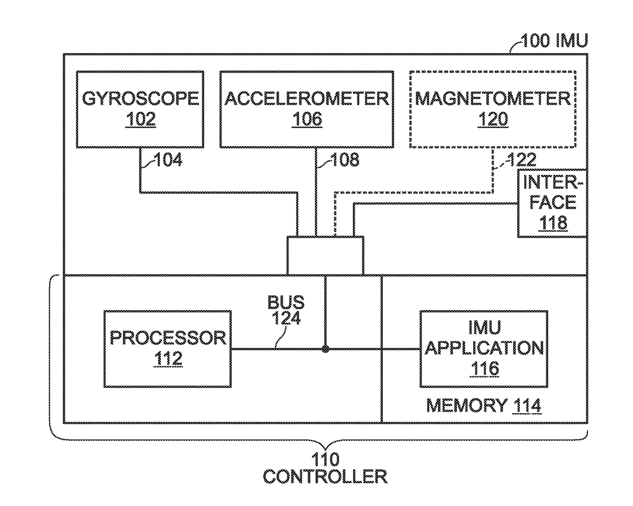
[0024]FIG. 1 is a schematic block diagram of an inertial measurement unit (IMU). The IMU 100 comprises a gyroscope 102 having an output on line 104 to supply gyroscopic readings. An accelerometer 106 has an output on line 108 to supply accelerometer readings. The IMU 100 further comprises a controller 110, with a processor 112, a non-transitory memory 114, and an IMU application 116 residing in the non-transitory memory. The IMU application 116 comprises a sequence of processor executable instructions for calculating a gyroscopic quaternion in response to gyroscopic readings, and calculating a field quaternion using accelerometer readings when an accelerometer reading is about equal to gravity (1 G). The IMU application 116 estimates angular orientation errors due to IMU angular velocity and linear acceleration, and uses the angular orientation errors to selectively mix the gyroscopic quaternion and field quaternion to supply a current sample quaternion via interface 118. Alternativ...


PUM


Abstract

A system and method are provided for determining the orientation of an inertial measurement unit (IMU). The method calculates a gyroscopic quaternion, and when the IMU accelerometer reading is about equal to gravity (1 G), a field quaternion is calculated using IMU accelerometer readings. Estimates are made of angular orientation errors due to IMU angular velocity and linear acceleration, and these angular orientation errors are used to selectively mix the gyroscopic quaternion and field quaternion to supply a current sample quaternion. Alternatively, if the accelerometer reading is not about equal to 1 G, the gyroscopic quaternion is used as the current sample quaternion. In one aspect, IMU gyroscope readings and IMU accelerometer readings are calibrated in response to determining a lack of IMU movement. Near-zero gyroscope reading jitter is removed by setting the IMU gyroscopic reading to zero, when the gyroscopic reading is near zero.

Description

BACKGROUND OF THE INVENTION[0001]1. Field of the Invention[0002]This invention generally relates to location and movement determination and, more particularly, to systems and methods for determining the spatial orientation of an inertial measurement unit (IMU).[0003]2. Description of the Related Art[0004]Inertial measurement units, also called inertial motion units, are devices that facilitate continuous computation of the orientation of the objects to which they are attached. By way of example, IMUs may be attached to human body limbs, robotic appendages, or aerial drones. IMUs typically have multiple single- or multi-axis sensors, such as gyroscopes, accelerometers, and magnetometers. Ideally, the accelerometer and magnetometer respectively measure the field strength of the local gravitational and magnetic fields produced by a reference object, such as Earth, and in turn produce sensor field strength readings. The gyroscope measures the rotational speed of the sensor relative to i...

Claims


Application Information

Patent Timeline
Patent Type & Authority Patents(United States)
IPC IPC(8): G01C21/16
CPCG01C21/165G01C21/16G01C21/188
Inventor HALLBERG, BRYAN
Owner SHARP KK