Supercharge Your Innovation With Domain-Expert AI Agents!

Wireless load control system

a control system and load technology, applied in the field of load control system, can solve the problems of difficult replacement, inability to maintain time and date information, and large batteries, and achieve the effect of disabling the timeclock schedul

Active Publication Date: 2017-12-26
LUTRON TECH CO LLC
View PDF34 Cites 32 Cited by
  • Summary
  • Abstract
  • Description
  • Claims
  • Application Information

AI Technical Summary

Problems solved by technology

However, batteries are often large and costly and may be difficult to replace.
In addition, batteries will eventually run out, at which time, the controller will be unable to maintain the time and date information to then correctly execute the timeclock schedule.

Method used


Image

  • Wireless load control system
  • Wireless load control system
  • Wireless load control system

Examples


Embodiment Construction

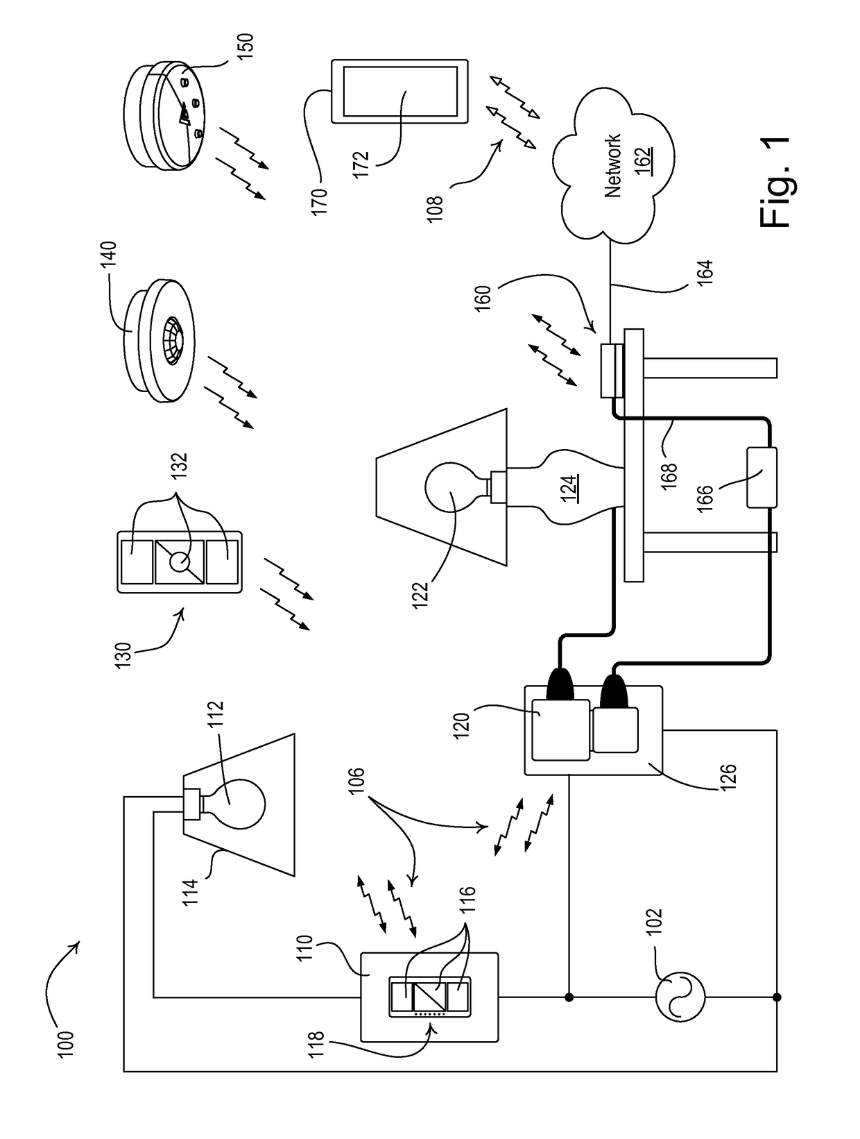
[0015]FIG. 1 is a simple diagram of an example load control system 100 (e.g., a lighting control system) for controlling the amount of power delivered from an alternating-current (AC) power source to one or more electrical loads. The load control system 100 may comprise a first load control device, e.g., a wall-mounted dimmer switch 110, coupled in series electrical connection between the AC power source 102 and a first lighting load, e.g., a first light bulb 112 installed in a ceiling mounted downlight fixture 114. Alternatively, the first light bulb 112 could be installed in a wall-mounted lighting fixture or other lighting fixture mounted to another surface. The dimmer switch 110 may be adapted to be wall-mounted in a standard electrical wallbox. The load control system 100 may also comprise a second load control device, e.g., a plug-in load control device 120, coupled in series electrical connection between the AC power source 102 and a second lighting load, e.g., a second light...


PUM


Abstract

A wireless load control system for controlling one or more electrical loads comprises a wireless control device (e.g., a gateway device) able to obtain a present time from a server via a network (e.g., the Internet), control the electrical loads according to a timeclock schedule, and disable the timeclock schedule if the present time is not able to be obtained from the server via the network. The wireless control device may also be able to obtain the present time from a digital message received from an external device (e.g., a smart phone or a tablet device) via the network. The wireless control device may be configured to receive a control signal indicating a power outage (e.g., from a battery backup device), and to operate in a low-power mode in response to receiving the control signal indicating the power outage.

Description

CROSS-REFERENCE TO RELATED APPLICATIONS[0001]This application is a non-provisional application of commonly-assigned U.S. Provisional Application No. 61 / 923,055, filed Jan. 2, 2014, entitled WIRELESS LOAD CONTROL SYSTEM, the entire disclosure of which is hereby incorporated by reference.BACKGROUND[0002]Field of the Disclosure[0003]The present disclosure relates to a load control system for controlling the amount of power delivered to an electrical load, and more particularly, to a wireless lighting control system for controlling the intensity of one or more lighting loads according to a timeclock schedule.[0004]Description of the Related Art[0005]Home automation systems, which have become increasingly popular, may be used by homeowners to integrate and control multiple electrical and / or electronic devices in their house. For example, a homeowner may connect appliances, lights, blinds, thermostats, cable or satellite boxes, security systems, telecommunication systems, and the like to ...

Claims


Application Information

Patent Timeline
Patent Type & Authority Patents(United States)
IPC IPC(8): G05F1/66H04W4/00G05B15/02H04W4/70
CPCG05F1/66H04W4/005G05B15/02G05B2219/2642H04W4/70
Inventor BARD, BENJAMIN F.DOLAN, DAVID J.MANN, TIMOTHYRIEDL, CHRISTOPHER M.
Owner LUTRON TECH CO LLC
Features
  • R&D
  • Intellectual Property
  • Life Sciences
  • Materials
  • Tech Scout
  • Unparalleled Data Quality
  • Higher Quality Content
  • 60% Fewer Hallucinations
Learn More