Mobile large manipulator

a manipulator and large-scale technology, applied in the direction of cranes, instruments, transportation and packaging, etc., can solve the problems of insufficient support, obstacles at the site of use, and the support arms cannot be fully extended

Active Publication Date: 2018-01-02
FRIEDRICH WILH SCHWING GMBH
View PDF9 Cites 3 Cited by
  • Summary
  • Abstract
  • Description
  • Claims
  • Application Information

AI Technical Summary

Benefits of technology

[0006]Thus, the problem which the invention proposes to solve is to provide a mobile large manipulator which allows the machine operator to find an optimal operating positio...

Problems solved by technology

However, it is often the case that the support arms cannot be fully extended, since the places of use of the large manipulators are often too narrow.
For example, there are obstacles at the site of use or the ground is not strong enough to support the machine.
As a whole, this results in a restricted operating range of the mast.
If this operating range of the mast is exceeded, the danger exists of the large manipulator tipping over.
The problem still occurs for the machine operator when driving up to a concrete laying site of finding a suitable operating position of the large manipulator, so that the concrete laying surface can be optimally reached with the mast arm.
It is very difficult to assess a sui...

Method used


Image

  • Mobile large manipulator
  • Mobile large manipulator
  • Mobile large manipulator

Examples


first embodiment

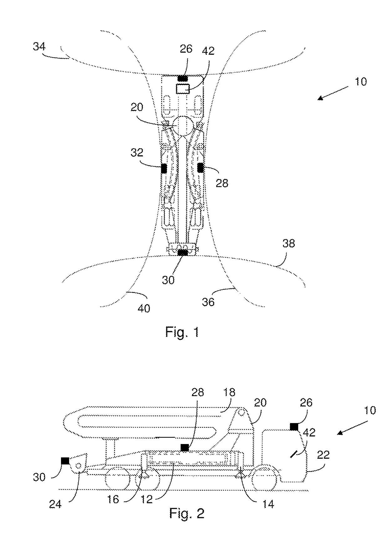
[0043]FIG. 1 shows a top view of a large manipulator 10 according to the invention in a The large manipulator 10 comprises a chassis 12, two front 14 and two 16 rear support arms which can be supported on a base surface by way of extendable support legs, which are arranged on the chassis and can be fully or partly extended from a travel position to a support position, and a foldout mast arm 18, having a turntable 20 which can pivot around a vertical axis and a plurality of mast segments hinged to each other. Moreover, the large manipulator 10 has a program-controlled positioning aid, with which it is possible to put out a graphical representation of surrounding image data on a monitor screen 42, the operating range of the mast arm 18 being also visualized.

[0044]The operator of the large manipulator for example can first specify a desired operating range 60 of the mast arm 18, which then necessitates a particular support configuration. In the visualization, the large manipulator 10 ...

second embodiment

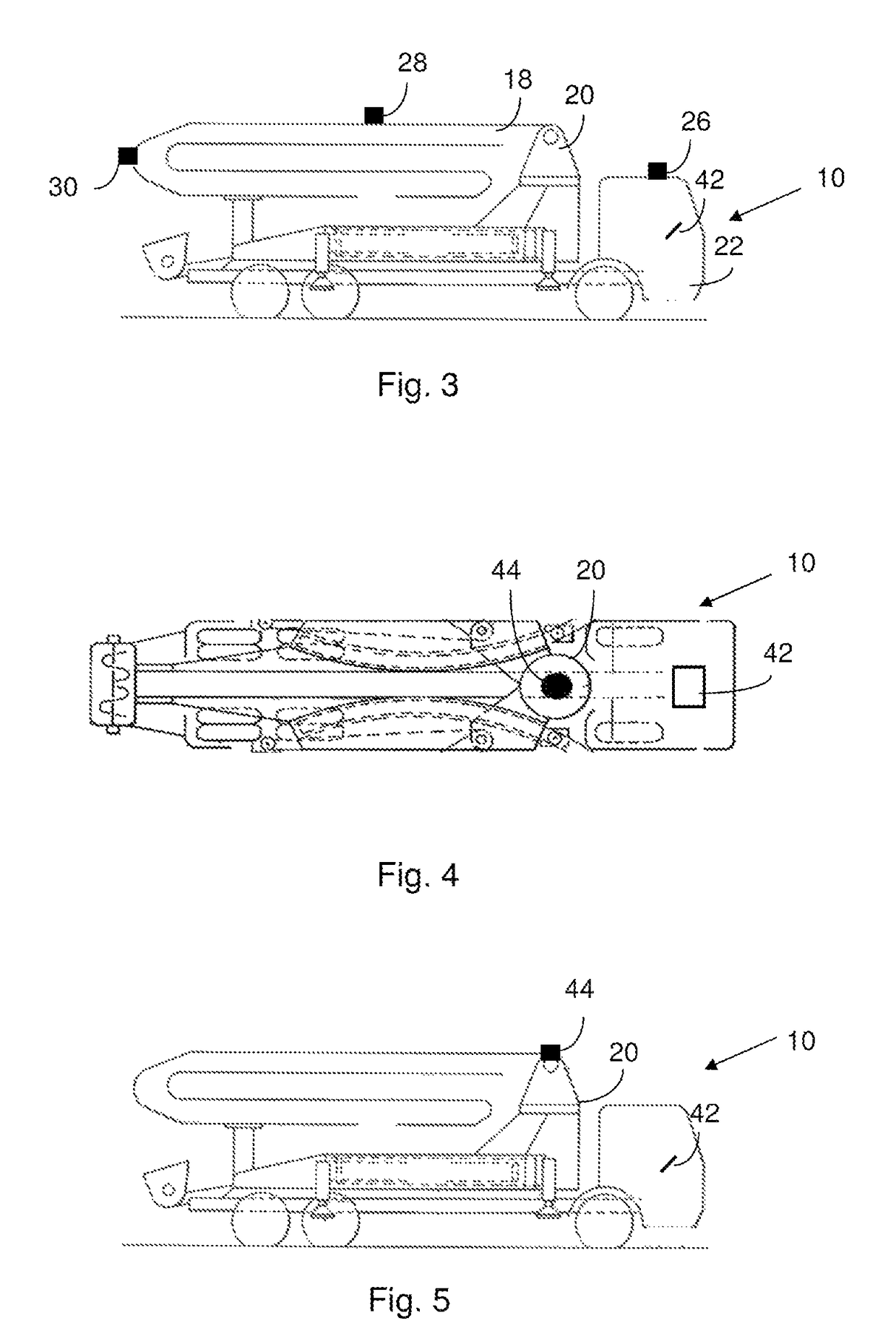
[0049]FIG. 3 shows a schematic side view of a large manipulator 10 according to the invention in a In order to improve the range of the cameras 26, 28, 30, 32, they are arranged here as far up as possible on the large manipulator 10. The front camera 26 is arranged on the driver cabin 22, the other three cameras 28, 30, 32 are arranged on the mast arm 18. Thanks to such an arrangement of the cameras 26, 28, 30, 32, the machine operator obtains a better overview of the construction site. In order to be able to dispense with a costly use of cables for the cameras 26, 28, 30, 32, the cameras 26, 28, 30, 32 are preferably linked by a radio connection to the positioning aid.

third embodiment

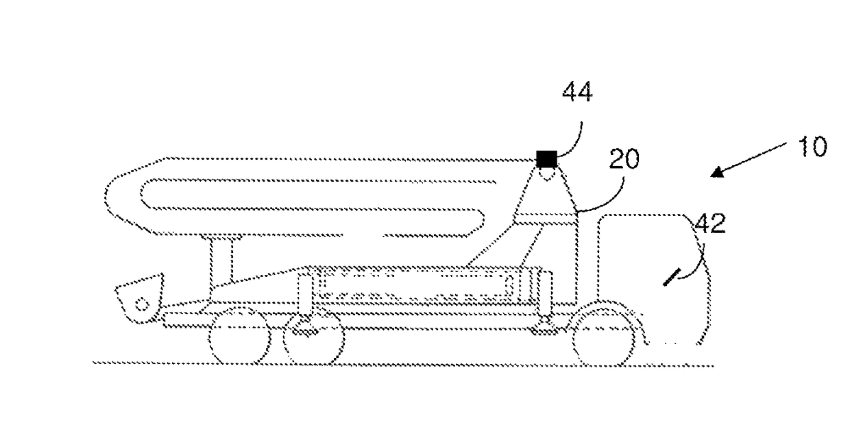
[0050]FIG. 4 shows a schematic top view of a large manipulator 10 according to the invention in a The camera 44 is arranged on the turntable 20. The turntable 20 constitutes the midpoint of the mast arm 18 and thus also the midpoint of the operating range 60.

[0051]Ideally the camera 44 is a camera with 360° panoramic view. Advantageously, a costly computerized superimposing of pictures of different cameras is unnecessary here. Two cameras can also be arranged on the turntable 20. These are then preferably arranged at the sides, the right and left side of the turntable 20.

[0052]FIG. 5 shows a schematic side view of a large manipulator 10 according to the invention in the third embodiment as per FIG. 4. The 360° camera 44 is arranged on the turntable 20.


PUM


Abstract

A large manipulator includes a chassis, at least two front support arms, and at least two rear support arms. The support arms are coupled to corresponding extendable support legs that are each coupled to the chassis and that are each configured to be extended between a travel position and a support position. The large manipulator further includes a mast arm with a turntable coupled to the chassis. An operating range of the mast arm is dependent upon the support positions of the extendable support arms. The large manipulator further includes a computer with a monitor and a program-controlled positioning aid. The positioning aid is configured to generate a graphical representation of surrounding image data on the monitor. The operating range of the mast arm is visualized in the graphical representation.

Description

TECHNICAL FIELD[0001]The invention concerns a mobile large manipulator as well as a method for the program-controlled assistance of the positioning of a large manipulator.BACKGROUND OF THE INVENTION[0002]Large manipulators are known from the prior art (see, e.g., EP 2 038 493 B1). In particular, they comprise a chassis, two front and two rear support arms that can be supported on a base surface by way of extendable support legs, which are arranged on the chassis and can be extended entirely or partly from a travel position to a support position, and a foldout mast arm, which has a turntable able to pivot around a vertical axis and a plurality of mast segments which are hinged to each other.[0003]With fully extended and propped up support arms, a rotation of the fully unfolded mast arm through 360° is usually possible. Thus, on the whole, it is possible to achieve a circular range around the large manipulator with the mast arm without the danger of the large manipulator tipping over....

Claims


Application Information

Patent Timeline
IPC IPC(8): G06F19/00E04G21/04B66C15/04B66C23/78
CPCE04G21/0463B66C15/045E04G21/0436E04G21/0445B66C23/78B64C2201/127B64U2101/30
Inventor VIERKOTTEN, REINERSCHNITTKER, JOSEPH
Owner FRIEDRICH WILH SCHWING GMBH
Why Eureka
Try Eureka