Transmitting device, receiving device, and transmitting and receiving system

a technology of transmitting device and receiving device, which is applied in the direction of code conversion, phase-modulated carrier system, instruments, etc., can solve the problems of increasing the overall power consumption, not being suitable for implementation on wireless sensor nodes, and increasing the power consumed by compression operations

Active Publication Date: 2018-01-02
FUJI ELECTRIC CO LTD +1
View PDF13 Cites 2 Cited by
  • Summary
  • Abstract
  • Description
  • Claims
  • Application Information

AI Technical Summary

Benefits of technology

[0009]If a matrix having random elements is used as the observation matrix Φ when the input digital signal x has the above mentioned sparsity, based on the observation matrix Φ, the basis transformation matrix Ψ, and the compressed digital signal d, by use of L1-norm minimization or the like, the original input digital signal x is able to be accurately decompressed.

Problems solved by technology

Data compression by these compression techniques requires many arithmetic operations, and thus is not suitable for implementation on wireless sensor nodes, for which low power consumption is demanded.
For example, if such data compression is applied to a wireless sensor node, power consumed by compression operations may become greater than the amount of reduction in the wireless transmission power and the overall power consumption may actually be increased.

Method used


Image

  • Transmitting device, receiving device, and transmitting and receiving system
  • Transmitting device, receiving device, and transmitting and receiving system
  • Transmitting device, receiving device, and transmitting and receiving system

Examples


first embodiment

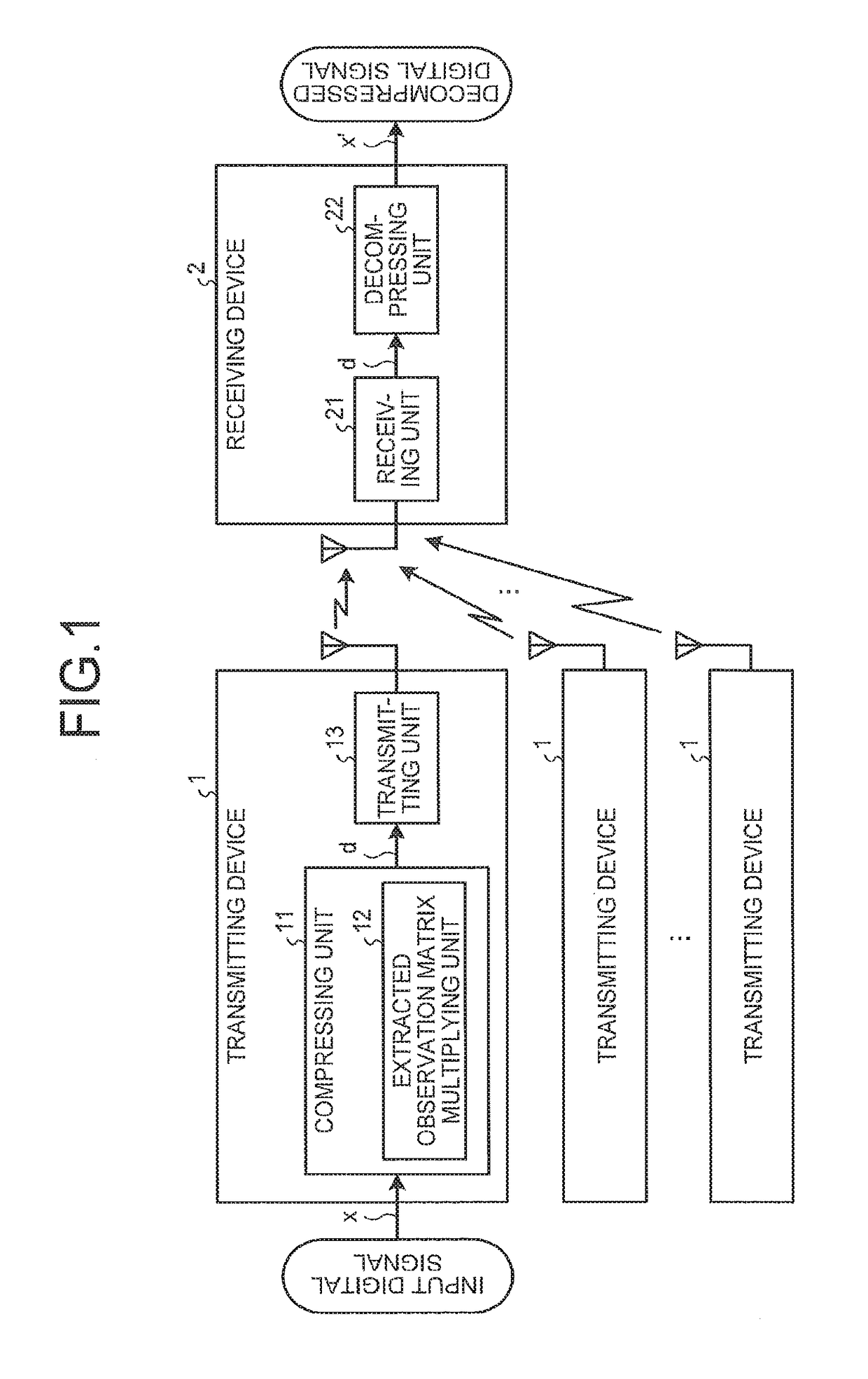
[0049]FIG. 1 is a block diagram illustrating an overall configuration of a transmitting and receiving system, which is a first embodiment of this invention. In this transmitting and receiving system, for example, an accelerometer not illustrated measures an acceleration component of vibration of a structure, and input digital signals x that have been converted into digital signals by an analog-digital converter not illustrated are respectively input to plural transmitting devices 1 corresponding thereto. In each of the transmitting devices 1, a compressing unit 11 generates a compressed digital signal d by compressing the input digital signal x, and a transmitting unit 13 transmits this compressed digital signal d to a receiving device 2 side. In the receiving device 2, a receiving unit 21 receives the compressed digital signal d transmitted from the transmitting device 1, and a decompressing unit 22 decompresses this compressed digital signal d and outputs it as a decompressed digi...

second embodiment

[0072]Next, a second embodiment of this invention will be described. In the above described first embodiment, the compressing unit 11 executes compression by multiplying the input digital signal x by the extracted observation matrix Φa, but the compressing unit 11 of this second embodiment first executes fast Walsh-Hadamard transform, and wirelessly transmits a portion corresponding to a specific frequency portion picked out from the converted digital signal as the compressed digital signal d.

[0073]FIG. 16 is a block diagram illustrating a configuration of the compressing unit 11 of a transmitting and receiving system, which is the second embodiment. This compressing unit 11 has a fast Walsh-Hadamard transform operation unit 31 and a specific frequency component extracting unit 32.

[0074]The fast Walsh-Hadamard transform operation unit 31 executes fast Walsh-Hadamard transform of an input digital signal x. Fast Walsh-Hadamard transform is a process of executing arithmetic processing ...

third embodiment

[0091]Next, a third embodiment of this invention will be described. In this third embodiment, the compression process and decompression process described in the first embodiment that achieve accurate decompression even if the sparsity is low, and the conventional compression process and decompression process that achieve accurate decompression when the sparsity is high, are made to be able to be switched over therebetween.

[0092]FIG. 25 is a block diagram illustrating a schematic configuration of a transmitting and receiving system, which is the third embodiment. It is different from the transmitting and receiving system described in the first embodiment in that a compressing unit 110 corresponding to the compressing unit 11 has a first compressing unit 111, a second compressing unit 112, and a transmission side switch over unit 113. The transmission side switch over unit 113 causes a compression process with respect to an input digital signal x to be processed by switching over betw...


PUM


Abstract

A transmitting device includes: a compressing unit configured to generate and output a compressed digital signal that has been compressed, by converting an input digital signal by use of a Walsh function and extracting a specific frequency component.

Description

CROSS-REFERENCE TO RELATED APPLICATION(S)[0001]This application is a continuation of PCT international application Ser. No. PCT / JP2014 / 084427 filed on Dec. 25, 2014 which designates the United States, incorporated herein by reference, and which claims the benefit of priority from Japanese Patent Application No. 2014-001251, filed on Jan. 7, 2014, incorporated herein by reference.BACKGROUND[0002]1. Field of the Invention[0003]The disclosure relates to a transmitting device, a receiving device, and a transmitting and receiving system, which enable accurate decompression even if the original input digital signal has low sparsity.[0004]2. Related Art[0005]In wireless sensor nodes, for which low power consumption is demanded, reducing the wireless transmission power, which largely accounts for the power consumption, is indispensable. One of techniques therefor is reducing the wireless transmission power by reducing the amount of data by data compression of transmission data.[0006]In gene...

Claims


Application Information

Patent Timeline
Patent Type & Authority Patents(United States)
IPC IPC(8): H03M7/30H04B1/04H04L27/22H04J11/00
CPCH04L27/22H04J11/00H04B1/04H03M7/3062G06F17/145H03M7/3068H04N1/32176H04J13/0048H04L1/1887
Inventor KAWAKAMI, HARUKIASAMI, TOHRUKAWAHARA, YOSHIHIROKISHIRO, MASAMIKUDO, TAKAHIRO
Owner FUJI ELECTRIC CO LTD
Why Eureka
Try Eureka