Chopped electrical energy converter

a technology of electrical energy converter and electrical component, which is applied in the direction of dc-dc conversion, power conversion system, instruments, etc., can solve the problems of high volume and weight cumbersome structure of electrical energy converter, etc., and achieve the reduction of effective current in electrical components, increase in the number of conversion modules, and double the frequency of output signals

Inactive Publication Date: 2018-01-09
FAIVELEY TRANSPORT TOURS
View PDF15 Cites 0 Cited by
  • Summary
  • Abstract
  • Description
  • Claims
  • Application Information

AI Technical Summary

Benefits of technology

[0018]Such a converter structure makes it possible to increase the chopping frequency on the input signal and on the output signals of the first and second output stage, thereby containing fewer passive energy storage power components and fewer transformers than a conventional converter structure. Therefore its volume and its weight are lower relative to the conventional structures for electrical energy converters.
[0019]Furthermore, the cost of a converter structure according to the invention is also lower than the cost of a conventional structure.
[0023]By virtue of the presence of at least two conversion modules, the frequency of the output signals is doubled and the effective currents in the electrical components are reduced both on the input signals and the output signals.
[0024]Furthermore, the greater the increase in the number of conversion modules, the higher the frequency of the output signals and the lower the effective currents in the electrical components.
[0031]Such circuits make it possible to reduce the switching losses of the associated switching means, further increasing the yield of the electrical energy converter.

Problems solved by technology

Such an electrical energy converter structure is cumbersome, its volume and its weight being high.

Method used


Image

  • Chopped electrical energy converter
  • Chopped electrical energy converter
  • Chopped electrical energy converter

Examples


Embodiment Construction

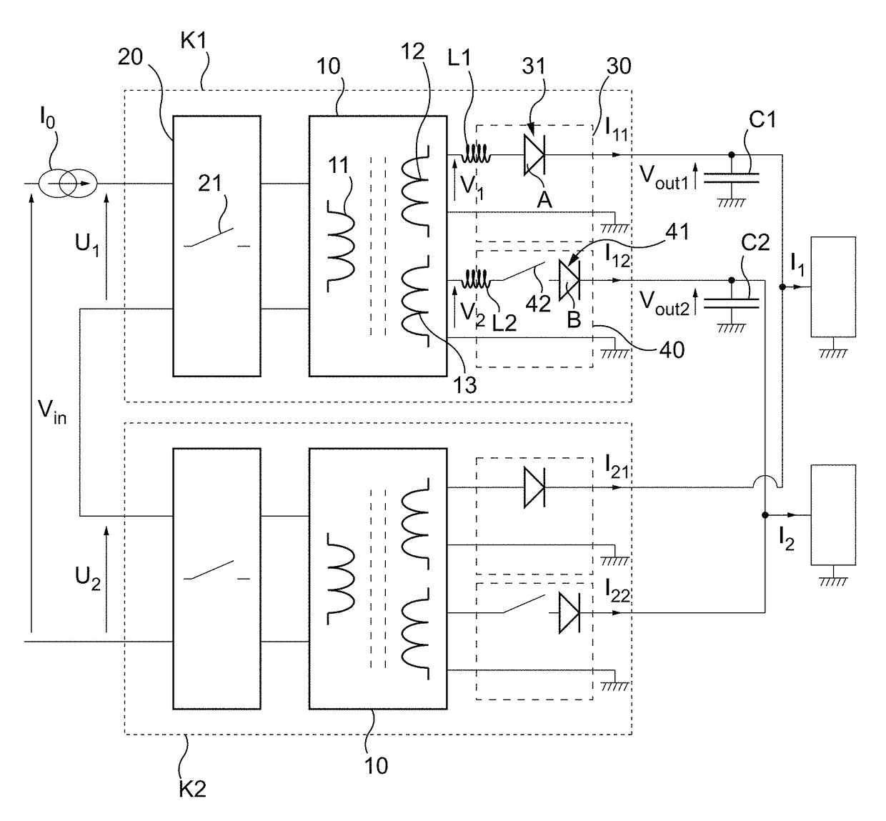
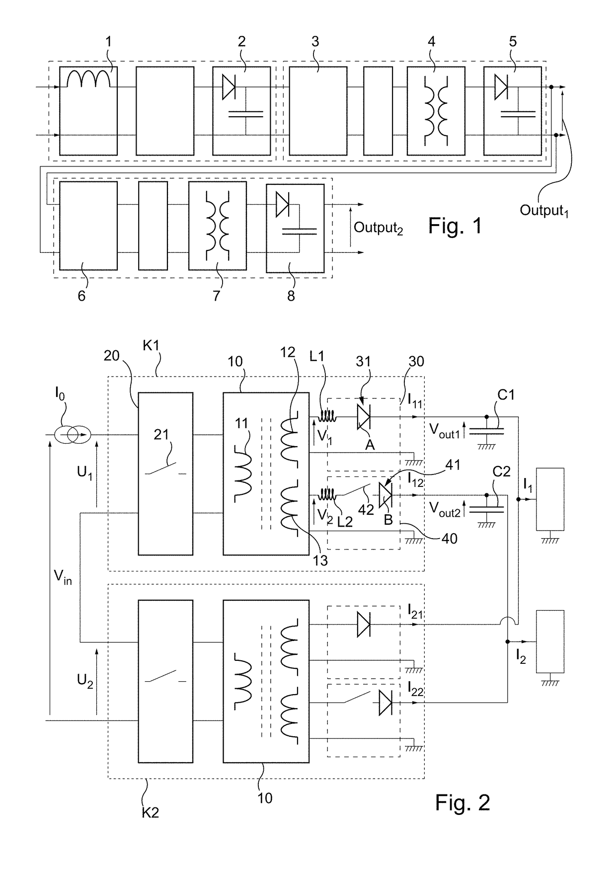
[0039]With reference to FIG. 2, an electrical energy converter in accordance with the invention will be described.

[0040]The energy converter illustrated by FIG. 2 generates two output signals Vout1, Vout2, from a signal Vin at its input. Here the output signals Vout1, Vout2 are voltages.

[0041]Of course, an energy converter in accordance with the invention can generate a higher number of output signals.

[0042]The described example comprises two conversion modules K1, K2. In this example the conversion modules K1, K2 are identical.

[0043]Each conversion module K1, K2 comprises a transformer 10 comprising a primary winding 11, a first secondary winding 12 and a second secondary winding 13. The transformer 10 generates a first output signal from the transformer V1 and a second output signal from the transformer V2, the first output signal from the transformer V1 being taken at the first secondary winding 12 and the second output signal from the transformer V2 being taken at the second sec...


PUM


Abstract

A chopped current input electrical energy converter includes at least one conversion module (K1, K2) generating at least one first output signal (Vout1) and one second output signal (Vout2) and including: a transformer (10), an input switching stage (20) controlling the transfer of electrical energy to the transformer (10), and at least one first output stage (30) and one second output stage (40), the first output stage (30) generating the first output signal (Vout1), and the second output stage (40) generating the second output signal (Vout2); the level of the first output signal (Vout1) reflected at a primary winding (11) of the transformer (10) is greater than the level of the second output signal (Vout2) reflected at the primary winding (11) of the transformer (10).

Description

BACKGROUND OF THE INVENTIONField of the Invention[0001]The present invention concerns a current input chopped electrical energy converter.[0002]More particularly it concerns an electrical energy converter comprising at least two electrically isolated outputs.Description of the Related Art[0003]A structure of such an electrical energy converter for general use is represented in FIG. 1.[0004]This energy converter comprises in particular a power inductor 1 connected at the input of the converter, a rectification stage 2, a switching stage 3 making it possible to allow or not allow the passage of energy to the primary winding of a transformer 4 and a second rectification stage 5 from which a first output Output1 is taken.[0005]Furthermore, a second output Output2 is generated from the first output Output1. To generate this second output Output2, a second switching stage 6 is mounted to the primary winding of a second transformer, 7 and a third rectification stage 8 is mounted to the out...

Claims


Application Information

Patent Timeline
Patent Type & Authority Patents(United States)
IPC IPC(8): H02M7/217H02M3/335H02M1/00
CPCH02M7/217H02M3/33561H02M3/33576H02M2001/0087H02M2001/008H02M2001/0074H02M1/0074H02M1/0087H02M1/008
Inventor PERON, BENOIT
Owner FAIVELEY TRANSPORT TOURS
Why Eureka
Try Eureka