PWM waveform generation method and device based on FPGA

A generation method and waveform technology, which is applied in the direction of instruments, computer control, simulators, etc., can solve the problems of unable to directly output PWM waveforms and few peripheral resources, so as to improve control stability, reduce hardware cost and complexity, and improve The effect of design reliability

Pending Publication Date: 2022-02-01
HUNAN AEROSPACE ELECTROMECHANICAL EQUIP & SPECIAL MATERIAL INST
View PDF4 Cites 0 Cited by
  • Summary
  • Abstract
  • Description
  • Claims
  • Application Information

AI Technical Summary

Problems solved by technology

[0003] In order to solve the problem that the peripheral resources of the existing DSP6713 and other data processing chips in the background technology are very few, and there is no motor control ePWM peripheral interface, so the problem that the PWM waveform cannot be directly output, the present invention provides a PWM waveform generation method based on FPGA

Method used


Image

  • PWM waveform generation method and device based on FPGA

Examples


Embodiment Construction

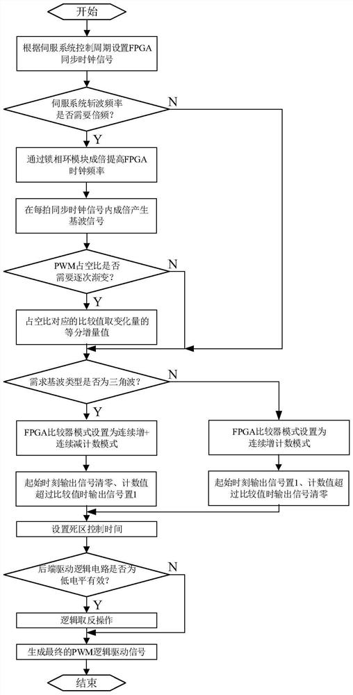
[0022] The present invention will be described in further detail below with reference to the accompanying drawings.

[0023] See figure 1 , A method of generating a PWM waveform based on FPGA, including steps:

[0024] S1, enabling the programmable logic device to generate the same synchronization clock signal as the control cycle of the servo control system;

[0025] S11: Judging whether it needs to be doubled to improve the servo system chopping frequency; Signal; if not, the process proceeds to step S2;

[0026] S12: It is judged whether or not the duty cycle of the PWM waveform will be graded.

[0027] S2, select the fundamental type that needs to be output:

[0028] If the base wave type is required to be a serrated wave, the comparator of the programmable logic device is configured to continuously increase the number mode; allows the programmable logic device to set the output signal "1" at the start time of the synchronization clock signal. The output signal is cleared when...


PUM


Abstract

The invention discloses a PWM waveform generation method and device based on an FPGA. The method comprises the following steps: S1, enabling a programmable logic device to generate a synchronous clock signal with the same control period as a servo control system; and S2, if the type of the fundamental wave needing to be output is a sawtooth wave, configuring a comparator of the programmable logic device to be in a continuous increasing counting mode; enabling the programmable logic device to set an output signal to be 1 at the starting moment of the synchronous clock signal, and resetting the output signal when a count value exceeds a comparison value corresponding to a duty ratio; if the type of the fundamental wave needing to be output is a triangular wave, configuring the comparator of the programmable logic device to be in a continuous increase/decrease counting mode; and resetting the output signal by the programmable logic device at the starting moment of the synchronous clock signal, and setting the output signal to be 1 when the count value exceeds the comparison value corresponding to the duty ratio. Compared with the prior art, data processing chips such as a DSP6713 chip and the like can directly output PWM waveforms.

Description

Technical field [0001] The present invention relates to the field of processor control, and more particularly to an FPGA-based PWM waveform generating method and apparatus. Background technique [0002] Traditional servo control systems use DSP28XX or STM32 series chips as master chips, DSP28XX or STM32 series chips have a rich peripheral resource, especially the EPWM peripheral interface of complementary PWM signals, dedicated to motor control applications. The DSP28XX or STM32 series chip is small, and the floating-point data processing power is far less than a data processing chip such as DSP6713, so it can only select DSP6713 data processing chip in some applications that require complex data or algorithm processing. However, the DSP6713's data processing chip has little resources, and there is no motor control EPWM peripheral interface, so the PWM waveform cannot be output. Inventive content [0003] To solve the background technology, the external DSP6713 has very small ex...

Claims


Application Information

Patent Timeline
Patent Type & Authority Applications(China)
IPC IPC(8): G05B19/042
CPCG05B19/0423G05B2219/25257
Inventor 张善交唐琼曹振兴
Owner HUNAN AEROSPACE ELECTROMECHANICAL EQUIP & SPECIAL MATERIAL INST
Why Eureka
Try Eureka