Aerodynamic golf club

Inactive Publication Date: 2018-02-06
FISCHER ALAN
View PDF23 Cites 1 Cited by
  • Summary
  • Abstract
  • Description
  • Claims
  • Application Information

AI Technical Summary

Benefits of technology

[0010]By employing structure of the foregoing type, an improved golf club is provided that has enhanced aerodynamic characteristics. In a disclosed embodiment a club head has a solid central section flanked on opposite sides by sections having a number of parallel channels that open on opposite sides of the club head to allow air passage from the front

Problems solved by technology

Effective use of these putters requires extreme precision and consistency.
Swinging golf clubs designed for gr

Method used


Image

  • Aerodynamic golf club
  • Aerodynamic golf club
  • Aerodynamic golf club

Examples


Example

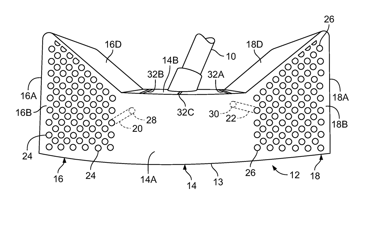
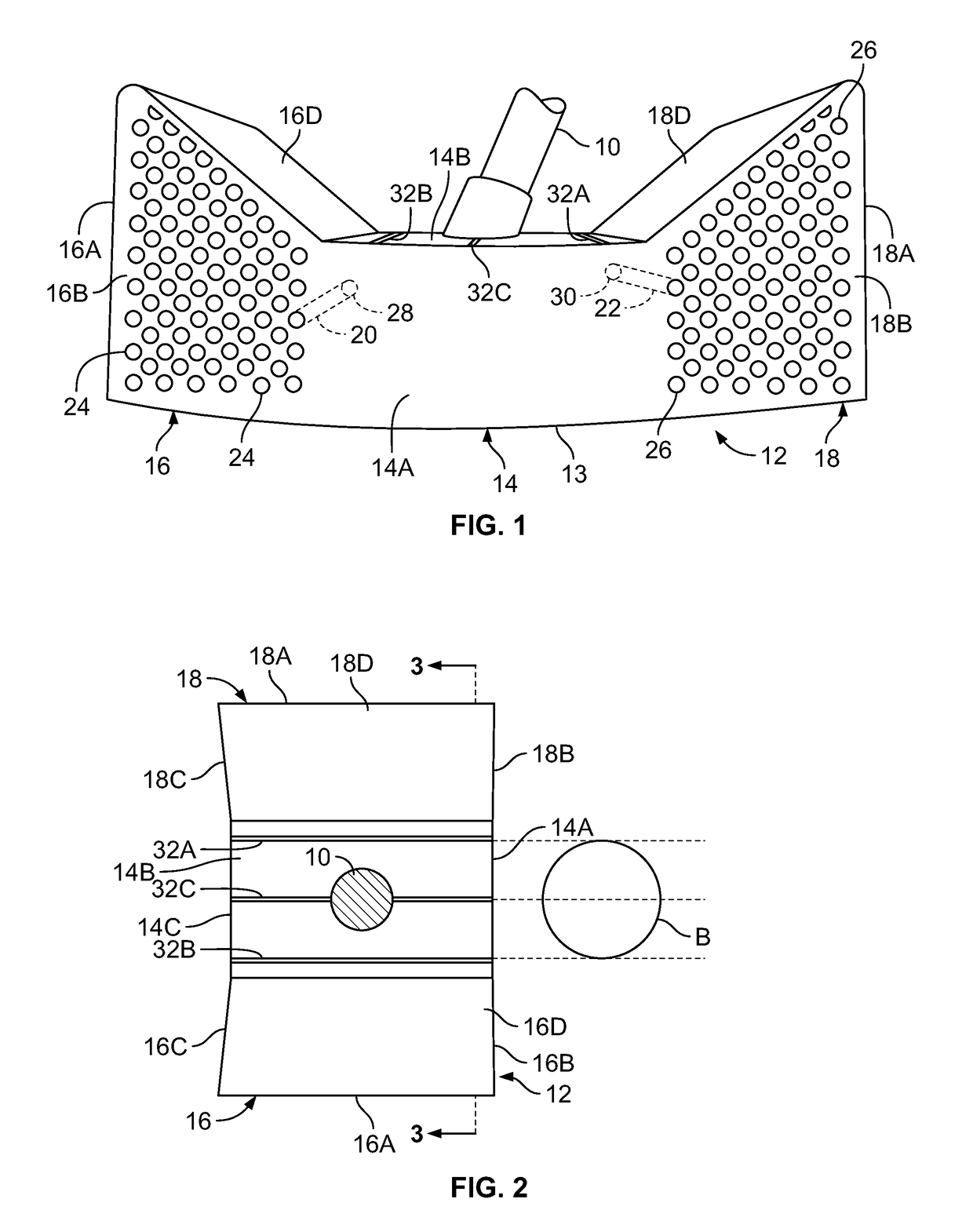
[0028]Referring to FIGS. 1-3, a golf club is shown with elongated shaft 10 attached at an angle to the top of club head 12 at section 14. Shaft 10 is, in this embodiment, an ordinary golf club shaft typically fitted on the distal end with a gripping sleeve (not shown). Shaft 10 is shown attached at the center of club head 12 (midway between the toe and heel of the club head), but in some embodiments may be offset from the center position. The bottom surface 13 of club head 12 is convexly curved in the toe to heel direction.

[0029]Club head 12 has a central section 14 that is flanked on opposite sides by integral flanking sections 16 and 18. Bottom surface 13 extends along sections 14, 16, and 18. The front of central section 14 has a striking face 14A that is wider than a golf ball. In this embodiment striking face 14A has a zero loft angle since this club head 12 is designed as a putter. Top surface 14B of central section 14 is marked with three parallel, equidistantly spaced indici...


PUM


Abstract

An aerodynamic golf club has a club head connected to an elongated shaft. The club head has a central section and contiguous thereto, a separated pair of flanking sections on opposite sides of the central section. The central section has a striking face in front and a rear surface in back. The pair of flanking sections each has a leading face in front and a trailing surface in back. The leading face of each of the flanking sections has a plurality of inlets. The trailing surface of each of the flanking sections has a plurality of outlets. Each of the flanking sections has a plurality of distinct channels. Each of the channels runs from a corresponding one of the plurality of inlets to an associated one of the plurality of outlets. The central section has an exposed top surface and an exposed bottom surface. Each of the top surface and the bottom surface extends up to the pair of flanking sections. The central section is impervious between its top surface and its bottom surface to internal airflow. The central section is impervious to internal airflow at the striking surface and above and below the striking surface.

Description

BACKGROUND OF THE INVENTION1. Field of the Invention[0001]The present invention relates to golf clubs, and in particular, clubs with aerodynamic features for improving club performance2. Description of Related Art[0002]Traditional golf clubs have a solid club head connected to an elongated shaft. The club head has a striking face extending substantially from the toe to the heel of the club head (i.e. from the distal to the proximal end of the club head). Club heads are made with various masses and loft angles, depending upon the desired trajectory and distance.[0003]When a golfer swings an iron or wood, the club head travels in an arc along an inclined plane. The face of the club tends to open on the backswing, close on the downswing, and then ideally strike the ball with the club face perpendicular to the desired flight path of the ball.[0004]A putter head has a much more abbreviated travel path and some players advocate moving the putter head in an arc along an inclined plane so t...

Claims


Application Information

Patent Timeline
IPC IPC(8): A63B53/02A63B53/04A63B53/00A63B60/52A63B60/00
CPCA63B60/52A63B53/007A63B53/0487A63B2053/0441A63B2060/006A63B69/3685A63B2071/0655A63B2225/01A63B60/50A63B53/0433A63B53/0441
Inventor FISCHER, ALAN
Owner FISCHER ALAN
Why Eureka
Try Eureka