Electrowetting system with stable movement

Inactive Publication Date: 2007-03-01
SAMSUNG ELECTRO MECHANICS CO LTD
View PDF11 Cites 16 Cited by
  • Summary
  • Abstract
  • Description
  • Claims
  • Application Information

AI Technical Summary

Benefits of technology

[0020] It is one object of the present invention to control the viscosity of an electrolyte solution constituting an electrowetting system by using

Problems solved by technology

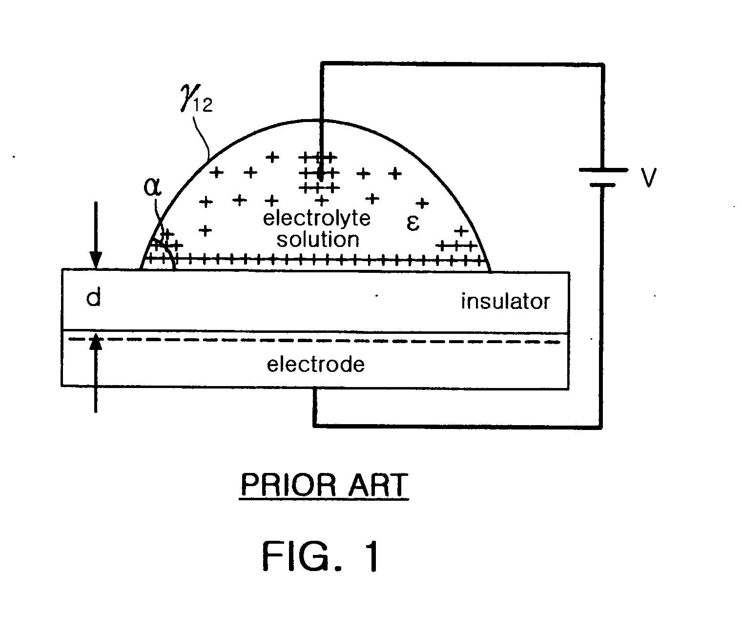
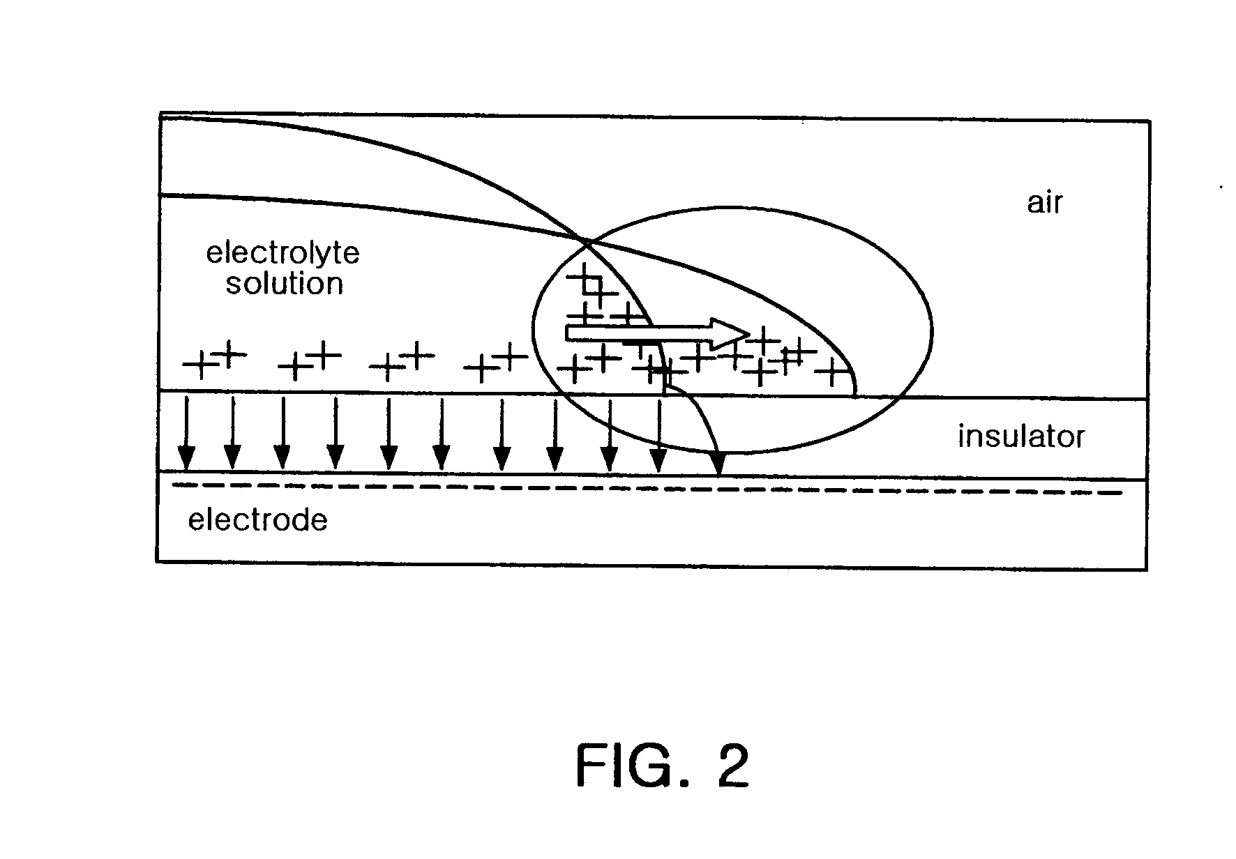
This phenomenon brings about an increase in the repulsive force between the charges, resulting in lowering of surface tension at the edges of liquid droplets.
Since general electrolyte soluti

Method used


Image

  • Electrowetting system with stable movement
  • Electrowetting system with stable movement
  • Electrowetting system with stable movement

Examples


Example

Example 1

[0048] 60% by weight of pure water, 10% by weight of LiCl and 30% by weight of 1,2-propanediol were mixed together to prepare a transparent electrolyte solution with a viscosity of 6.1. 1,6-Dibromohexane was mixed with a commercially available silicon oil to prepare an insulating solution with a viscosity of 11.8.

[0049] A cell for accommodating the electrolyte solution and the insulating solution comprises an upper part and a lower part. The upper part was made of a transparent material and an internal part of the upper part was coated with a metal film, through which a voltage was applied to the electrolyte solution. The lower part of the cell was made of the same material for the upper part, an internal part of the lower part in contact with the electrolyte solution was coated with a polymer insulator, and a metal film was coated under the insulator.

[0050] The electrolyte solution and the insulating solution were introduced into the cell to complete production of a liq...

Example

Comparative Example 1

[0053] 90% by weight of pure water and 10% by weight of LiCl were mixed together to prepare a transparent electrolyte solution with a viscosity of 1.9. 1,6-Dibromohexane was mixed with a commercially available silicon oil to prepare an insulating solution with a viscosity of 11.8.

[0054] The electrolyte solution and the insulating solution were used to produce a liquid lens in accordance with the procedure described in Example 1.

[0055] The photographs shown in FIGS. 5a and 5b are interference patterns showing states in which the electrolyte solution was moved in the liquid lens when no voltage was applied and 30 V was applied to the liquid lens, respectively.

[0056] The photographs shown in FIGS. 6a and 6b are interference patterns comparing the movement of (a) the electrolyte solution containing no polar solvent with that of (b) the electrolyte solution containing the polar solvent when 30 V was applied to each of the liquid lenses.

[0057] The interference pa...


PUM


Abstract

Disclosed herein is an electrowetting system using the electrowetting phenomenon. The electrowetting system comprises an electrolyte solution consisting of 30 to 89% by weight of water, 0.01 to 30% by weight of a salt and 10 to 60% by weight of a polar solvent having a dipole moment. According to the electrowetting system, the polar solvent added to increase the viscosity of the electrolyte solution stabilizes the movement of the electrolyte solution when a voltage is applied to operate the electrowetting system. In addition, high- or low-temperature reliability of the electrowetting system can be ensured by the use of the polar solvent.

Description

RELATED APPLICATIONS [0001] The present application is based on, and claims priority from, Korean Application Number 2005-77367, filed Aug. 23, 2005, the disclosure of which is incorporated by reference herein in its entirety. BACKGROUND OF THE INVENTION [0002] 1. Field of the Invention [0003] The present invention relates to an electrowetting system, and more particularly to an electrowetting system using an electrically conductive solution in which a polar solvent is contained to stabilize the movement of the solution and to increase the viscosity of the solution. [0004] 2. Description of the Related Art [0005] Electrowetting is a phenomenon wherein the surface tension of a liquid is altered using electrical charges present at the interface of the liquid. According to the electrowetting phenomenon, a high potential difference at the interface of a liquid is achieved when a thin insulator is present at the interface. [0006] The electrowetting phenomenon can be utilized to handle mi...

Claims


Application Information

Patent Timeline
IPC IPC(8): G02B3/12
CPCF04B17/00G02B26/005G02B3/14F04B19/006G01N27/416
Inventor JUNG, HA YONGCHOI, HEE SUNGYANG, JIN HYUCKBAE, JAE YOUNGKIM, JONG YUN
Owner SAMSUNG ELECTRO MECHANICS CO LTD
Why Eureka
Try Eureka