Roller-type one-way clutch

Inactive Publication Date: 2010-10-14
NSK WARNER
View PDF20 Cites 20 Cited by
  • Summary
  • Abstract
  • Description
  • Claims
  • Application Information

AI Technical Summary

Benefits of technology

[0008]Accordingly, an object of the present invention is to provide a roller type one-way clutch in which fluctuation in relative positions between accordion springs and an outer race is eliminated, so that the accordion springs are not slidingly contacted with an inne

Problems solved by technology

Particularly, in a roller type one-way clutch for a motor bike, since the number of rollers is small (for example, three or six), if all of the rollers are not engaged with the corresponding cam surfaces positively, a design torque capacity may not be obtained.
However, this document does not teach the fact that the springs are secured to the outer race.
If accordion springs are merely held with respect to the outer race, relative positions between the ac

Method used


Image

  • Roller-type one-way clutch
  • Roller-type one-way clutch
  • Roller-type one-way clutch

Examples


Example

First Embodiment

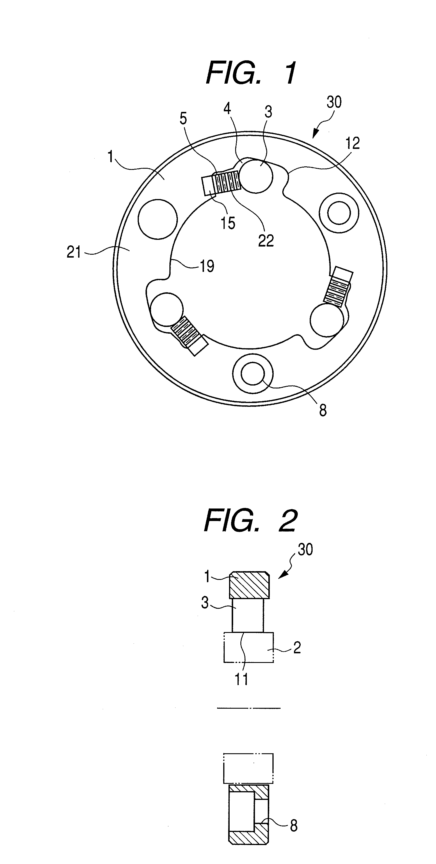
[0035]FIG. 1 is a front view of a roller type one-way clutch according to a first embodiment of the present invention and FIG. 2 is an axial sectional view of FIG. 1. In FIG. 2, an inner race 2 is shown by the imaginary line.

[0036]FIGS. 1 and 2 show a condition before rollers are engaged, i.e. an unlocked or idle rotation condition of the one-way clutch. In the illustrated embodiment, the inner race 2 is idly rotated.

[0037]As shown in FIG. 1, a roller type one-way clutch 30 comprises an annular outer race 1 provided at its inner periphery with pockets 4 formed as recessed portions having cam surfaces 12, an inner race 2 (shown by the imaginary line in FIG. 2) spaced apart from the outer race 1 radially inwardly and disposed coaxially with the outer race for a relative rotational movement and having an annular outer peripheral track surface 11, and a plurality of rollers 3 disposed within the corresponding pockets 4 and adapted to transmit torque between the outer per...

Example

Second Embodiment

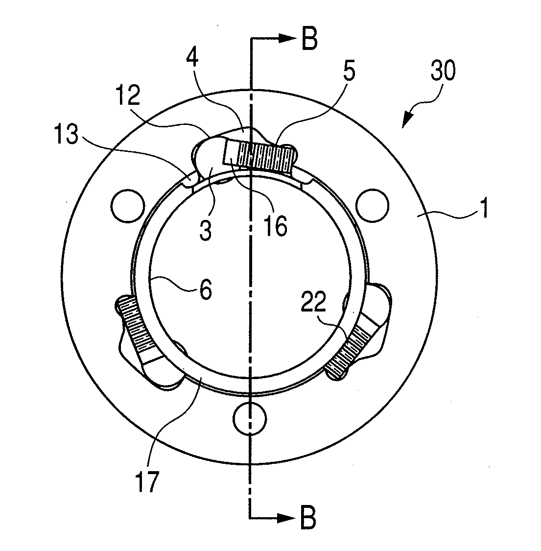
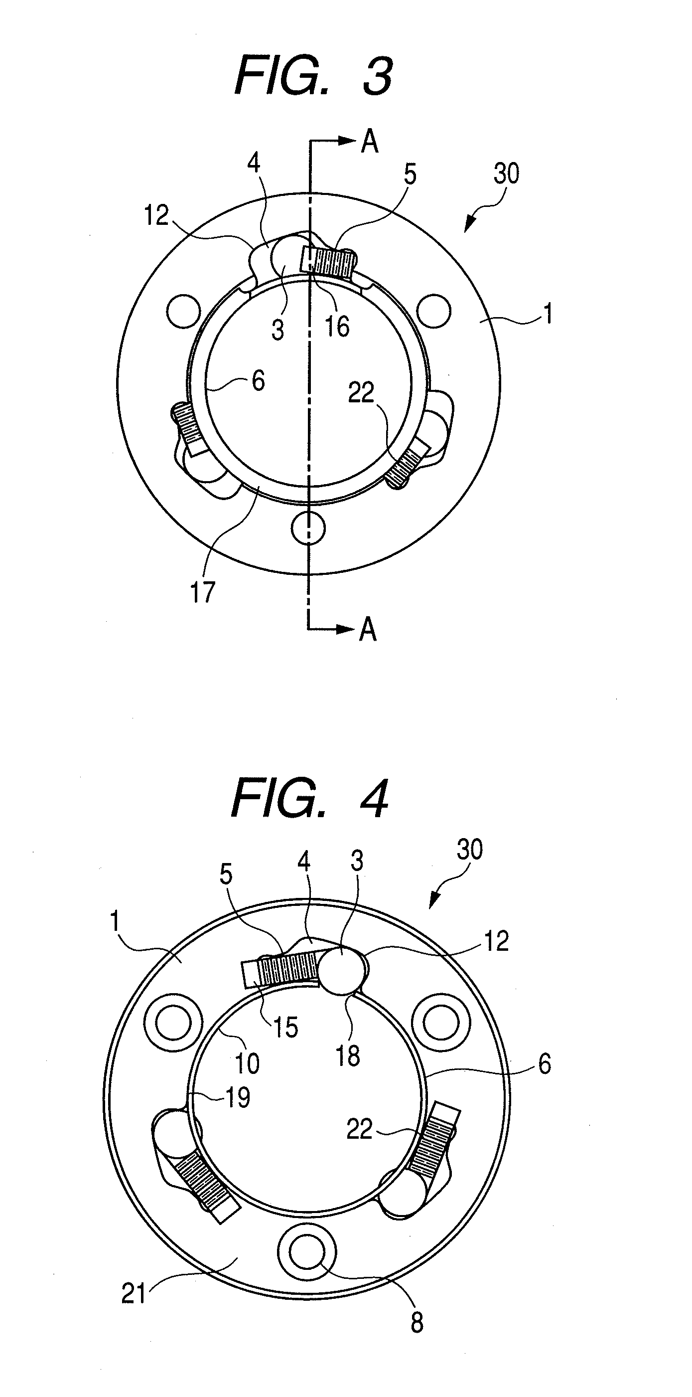
[0045]FIG. 4 is a front view of a roller type one-way clutch according to a second embodiment of the present invention, and FIG. 5 is a front view looked at from a rear side of FIG. 4. Further, FIG. 6 is an axial sectional view taken along the line B-B in FIG. 5. In the second embodiment, a cage 6 is provided at an inner diameter side of an outer race 1.

[0046]FIGS. 4 to 6 show a condition that rollers are engaged by cam surfaces, i.e. a locked condition that the one-way clutch is engaged under a high load.

[0047]As shown in FIGS. 4 and 5, the one-way clutch 30 comprises a cage 6 for holding rollers 3, and the cage 6 has a cylindrical portion 10 and an annular flange portion 17 extending radially outwardly from an axial one end of the cylindrical portion 10. Further, the cage 6 has windows 18 extending through the cage in a radial direction, and the number of the windows corresponds to the number of the rollers 3. Incidentally, in FIG. 5, the flange portion 17 is show...


PUM


Abstract

The present invention provides a roller type one-way clutch comprising an outer race in which pockets provided at their inner surfaces with cam surfaces are formed, an inner race spaced apart from the outer race in a radial inner diameter side and disposed coaxially with the outer race for a relative rotational movement and having an annular outer peripheral track surface, a roller disposed within the pocket to be engaged with the cam surfaces and adapted to transmit torque between the outer race and the inner race, and an accordion spring disposed within the pocket and adapted to bias the rollers to be engaged with the cam surfaces, and wherein one end of each accordion spring is secured to an axial end face of the outer race.

Description

TECHNICAL FIELD[0001]The present invention relates to a roller type one-way clutch used as a part such as a torque transmitting member or a back stopper in a driving apparatus of an automobile, an industrial machine or the like, for example.BACKGROUND ART[0002]In general, a roller type one-way clutch is constituted by an outer race, an inner race disposed coaxially with the outer race, a plurality of rollers disposed between an outer peripheral surface of the inner race and an inner peripheral cam surface of the outer race and adapted to transmit torque, and springs contacted with the rollers at an idle rotation side.[0003]With this arrangement, in the one-way clutch, the inner race is rotated only in one direction with respect to the outer race by a cam mechanism constituted by the rollers and the cam surface. That is to say, the inner race is designed so that the inner race is idly rotated with respect to the outer race in one direction and serves to transmit rotational torque to ...

Claims


Application Information

Patent Timeline
IPC IPC(8): F16D41/00
CPCF16D41/067F16D41/066
Inventor SHIRATAKI, HIROBUMIOKUMA, SHINYAANDO, TOMOHARU
Owner NSK WARNER
Why Eureka
Try Eureka