Battery driven mobile drawing device, including electromagnetic induction and capacitive position detectors and a control circuit for causing a parameter setting area to be displayed, and a test drawing area to be displayed transparently, superimposed, on a portion of a drawing in an image display area of a display, for rendering a drawing using an electronic pen

a mobile drawing and control circuit technology, applied in the field of drawing devices, can solve the problems of difficult to secure a sufficiently large parameter setting area, difficult to have a large display area for an image for verification of the adjustment effect, and difficult to enable desired parameters to be specified with ease, and display the effect of eas

Active Publication Date: 2018-02-06
WACOM CO LTD
View PDF28 Cites 0 Cited by
  • Summary
  • Abstract
  • Description
  • Claims
  • Application Information

AI Technical Summary

Benefits of technology

[0012]The drawing device performs a display process such that a portion of the image display area appears through the test drawing area. Therefore, rendering a test drawing in the test drawing area enables drawing information according to parameters set at the time of rendering the test drawing to be displayed superimposed on the drawing being displayed. This makes it possible to compare the test drawing information and the drawing displayed in the test drawing area, thus enabling desired parameters to be specified with ease.
[0013]Further, the drawing device displays the test drawing area in a visually identifiable manner in the image display area of the display device. As a result, the boundaries of the drawing in the image display area of the display device can be explicitly specified and compared to drawing information in the test drawing area generated using the indicator. This makes it possible to compare drawing information at the time of rendering a test drawing and a drawing being displayed with ease.
[0014]The display device performs a display process that displays test drawing information including parameters that can be set while a test drawing is rendered in a test drawing area that is superimposed on a drawing, which enables an image of the test drawing to be compared to an image of the drawing and provides an easy means of specifying desired parameters.

Problems solved by technology

When the parameters are specified with the parameter setting area appearing at the upper or left edge portion of the screen, it is difficult to have a large display area for the parameter setting area if a large display area is used for the drawing image.
In the case of a battery-driven mobile drawing device with a relatively small screen size, it is much more difficult to secure a sufficiently large parameter setting area.
Although the image data output device disclosed in Patent Document 1 enables verification of an adjustment effect resulting from the input of an adjustment value for the image, it is difficult to have a large display area for an image for verification of the adjustment effect.

Method used


Image

  • Battery driven mobile drawing device, including electromagnetic induction and capacitive position detectors and a control circuit for causing a parameter setting area to be displayed, and a test drawing area to be displayed transparently, superimposed, on a portion of a drawing in an image display area of a display, for rendering a drawing using an electronic pen
  • Battery driven mobile drawing device, including electromagnetic induction and capacitive position detectors and a control circuit for causing a parameter setting area to be displayed, and a test drawing area to be displayed transparently, superimposed, on a portion of a drawing in an image display area of a display, for rendering a drawing using an electronic pen
  • Battery driven mobile drawing device, including electromagnetic induction and capacitive position detectors and a control circuit for causing a parameter setting area to be displayed, and a test drawing area to be displayed transparently, superimposed, on a portion of a drawing in an image display area of a display, for rendering a drawing using an electronic pen

Examples


first example

[0132]FIG. 11 illustrates a first example of an operation for requesting the displaying of the parameter setting menu. In this first example, an area 34 is provided to accept an operation for requesting the displaying of the parameter setting menu 80 at the center of the upper edge portion of the display screen 33 of the drawing device 10. Touching (or tapping) the area 34 with the electronic pen 23 or with a finger serves as an operation for requesting the displaying of the parameter setting menu 80. It should be noted that the parameter item list bar 83 of the parameter setting menu 80 is not shown in FIG. 11 for convenience of description. The same is true for the examples given below.

[0133]In this case, the electronic pen 23 is used primarily to make a drawing operation. For clear distinction from a drawing operation in this example, touching (or tapping) the area 34 with the electronic pen 23 while pressing and holding the side switch 24 in particular serves as the operation fo...

second example

[0136]FIGS. 12 and 13 are diagrams used to describe a second example of an operation for requesting the displaying of the parameter setting menu. In the second example, as shown in FIG. 12, a gesture operation of the user moving the electronic pen 23 from top to bottom across the area 34 that is adapted to accept the operation for requesting the displaying of the parameter setting menu 80 serves as an operation for requesting the displaying of the parameter setting menu 80. Also in this example, the user makes a gesture operation of moving the electronic pen 23 from top to bottom while pressing and holding the side switch 24 for explicit distinction from a drawing operation.

[0137]Further, a gesture operation of the user moving a finger from top to bottom across the area 34 adapted to accept an operation for requesting the displaying of the parameter setting menu 80 similarly serves as an operation for requesting the displaying of the parameter setting menu 80.

[0138]In the second exa...

third example

[0141]FIG. 14 is a diagram for describing a third example of an operation for requesting the displaying of the parameter setting menu. In the third example, pressing only the pushbutton 63 does not serve as an operation for requesting the displaying of the parameter setting menu. Instead, in the third example, an operation of touching or tapping an arbitrary position of the display screen 33 by the electronic pen 23 while pressing and holding the pushbutton 63 serves as an operation for requesting the displaying of the parameter setting menu.

[0142]In the case of the third example, a touch operation (or tap operation) accompanied by pressing of the pushbutton 63 serves as an operation for requesting the displaying of the parameter setting menu.

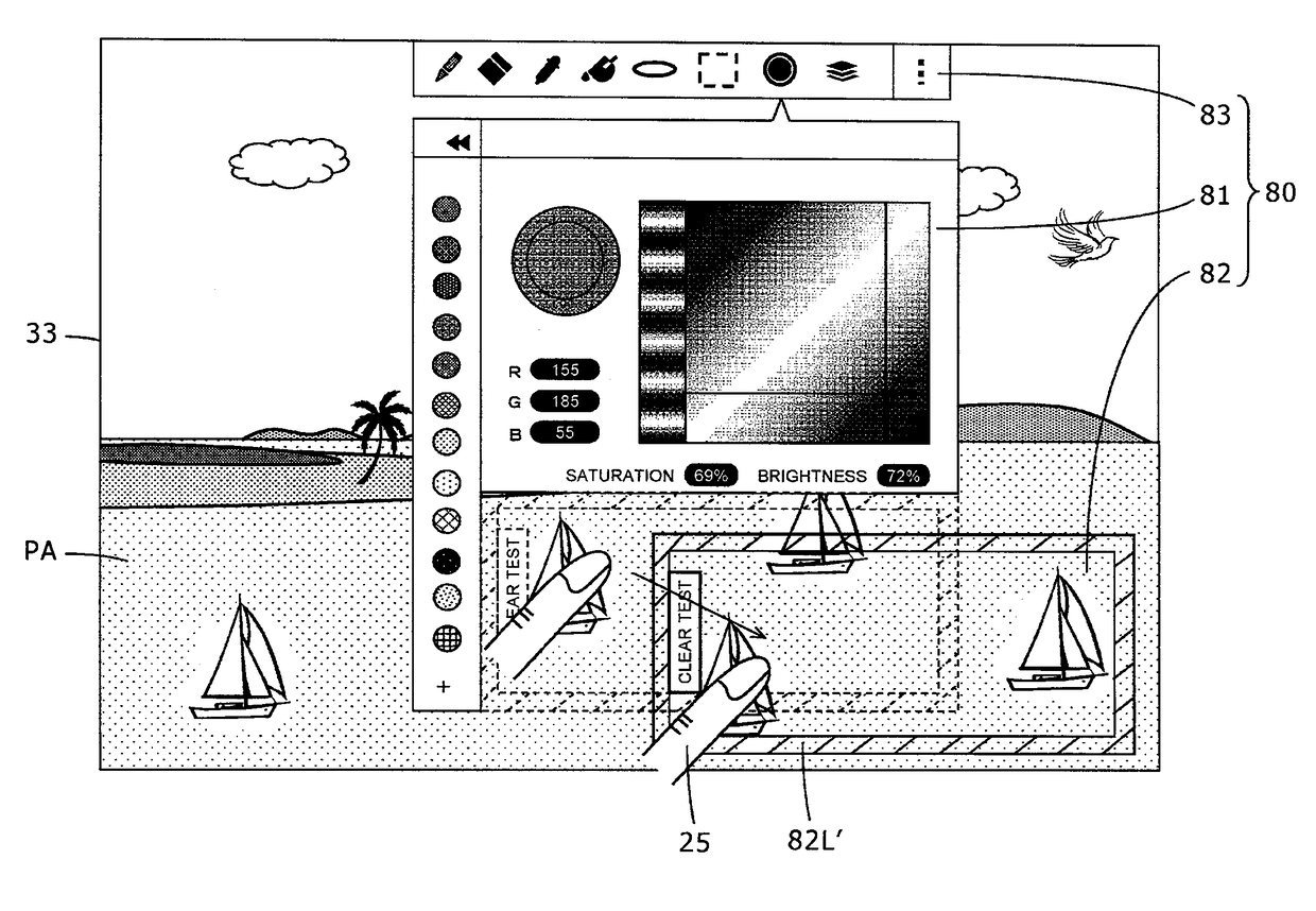
[0143]Then, in the case of the third example in particular, the image of the parameter setting menu 80 is displayed superimposed on the drawing image PA on the display screen 33 in such a manner that the position touched or tapped by the electr...


PUM


Abstract

A drawing device includes a sensor arranged in a superimposed relationship with a display device and having an indicator operation detection area sized to detect indictor operations in the image display area of the display device; a memory that stores drawing information; and a control circuit that renders a drawing in the image display area of the display device based on the drawing information stored in the memory. The control circuit causes a test drawing area and a parameter setting area to be displayed superimposed on the drawing image that is displayed in response to a detection, by the sensor, of an indication operation by the indicator, the test drawing area enabling a drawing operation to be performed using the indicator, the parameter setting area enabling changes to parameters of the drawing information generated by the drawing operation in the test drawing area using the indicator. The control circuit causes the test drawing area to be displayed transparently with a portion of the drawing appearing through the test drawing area.

Description

BACKGROUND[0001]Technical Field[0002]The present disclosure relates to a drawing device that renders an image of a drawing drawn using an indicator such as an electronic pen.[0003]Description of the Related Art[0004]A conventional drawing device can display an image of a drawing that includes graphics and text drawn with an indicator on a display device, and can store a drawing image displayed on the display device by detecting positions indicated by the indicator, which may be an electronic pen type of position indicator. The drawing device enables a user (e.g., a drawer) to render a desired drawing with various colors, line thicknesses, brightness levels, and the like by specifying parameters such as a pen thickness, a drawing color (e.g., a hue), and a brightness level for various portions of the drawing by based on inputs made with the indicator. Then, the drawing device stores the drawing image data in association with the specified parameters as drawing information. The drawin...

Claims


Application Information

Patent Timeline
Patent Type & Authority Patents(United States)
IPC IPC(8): G06F3/0354G06F3/0481G06T11/00G06F3/0484G06F3/048G06T3/40G09G5/377
CPCG06F3/03545G06F3/0481G06F3/04847G06T11/001G06F3/04845G06F2203/04804G06F3/046G06F3/0488
Inventor MARUOKA, ISAOLUPPI, MARCELLOADAM, SUSANDUNNIHOO, JARRODHIDAKA, JULI
Owner WACOM CO LTD
Why Eureka
Try Eureka