Method and device for operating a generator in a recuperation system of a motor vehicle

a recuperation system and generator technology, applied in the direction of electric generator control, dynamo-electric converter control, transportation and packaging, etc., can solve the problems of relative slowness and resource-minimizing setpoint specification, and achieve the effect of reducing co2 emissions, saving fuel, and cost advantages

Active Publication Date: 2013-08-29
ROBERT BOSCH GMBH +1
View PDF3 Cites 0 Cited by
  • Summary
  • Abstract
  • Description
  • Claims
  • Application Information

AI Technical Summary

Benefits of technology

The proposed generator current regulation / control function allows for autonomous and quick regulation without the need for external communication and regulation. The use of correlations between generator current, excitation current, generator voltage, and rotation speed avoids the need for current measurements, resulting in cost savings. The function also reduces fuel consumption and CO2 emissions in motor vehicles with recuperation function. The setpoint specification for the generator can be specified at relatively long time intervals, minimizing resource demands on external control units. The communication link remains possible using relatively slow (but economical) LIN buses. The function provides a more efficient and effective means of regulating generator current.

Problems solved by technology

This makes possible a relatively slow and thus resource-minimizing setpoint specification.

Method used


Image

  • Method and device for operating a generator in a recuperation system of a motor vehicle
  • Method and device for operating a generator in a recuperation system of a motor vehicle
  • Method and device for operating a generator in a recuperation system of a motor vehicle

Examples


Embodiment Construction

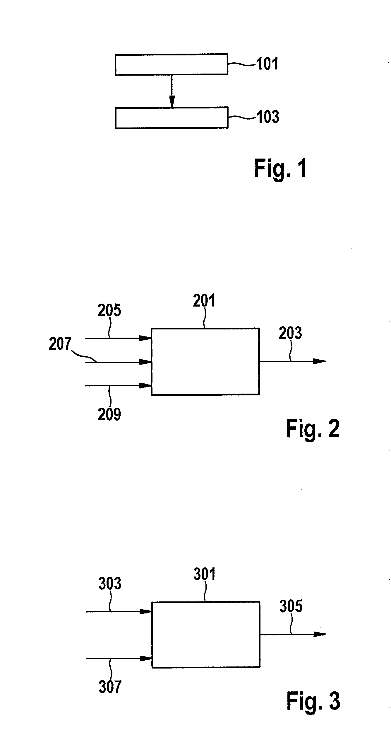
[0044]FIG. 1 is a schematic flow chart of an exemplifying embodiment of a method for operating a generator in a recuperation system of a motor vehicle.

[0045]In step 101, a setpoint for a mechanical torque of the generator is specified.

[0046]In step 103, a generator current of the generator for setting the specified mechanical torque of the generator is set.

[0047]FIG. 1 thus shows one possible method for generator current regulation, in which an actual value of the generator current is regulated to a setpoint of the generator current in order to set the specified mechanical torque of the generator. This regulation can be carried out in particular as a function of the present rotation speed of the generator. For example, the setpoint of the generator current is specified by way of a setpoint specification for the generator current.

[0048]FIG. 2 is a schematic block diagram of a first exemplifying embodiment of an apparatus 201 for operating a generator in a recuperation system. Apparat...


PUM


Abstract

A setpoint for a mechanical torque of a generator in a recuperation system of a motor vehicle is specified, and a generator current of the generator for setting the specified mechanical torque of the generator is set.

Description

BACKGROUND OF THE INVENTION[0001]1. Field of the Invention[0002]The present invention relates to the operation, in particular the control or regulation, of a generator in a recuperation system of a motor vehicle.[0003]2. Description of the Related Art[0004]In the interest of reducing CO2 discharge, and in light of constantly rising fuel prices, recuperation systems for reducing the fuel consumption and thus the CO2 emissions of motor vehicles are becoming increasingly significant.[0005]The motor vehicle's electrical system has a considerable influence on fuel consumption and thus on the CO2 emissions of the motor vehicle. An additional electrical power output of 100 W results, for example, in additional consumption of about 0.1 1 / 100 km in the New European Driving Cycle (NEDC). A 500 W vehicle electrical system load in this case signifies an additional 0.5 1 / 100 km of consumption.[0006]If the kinetic energy released upon braking, or the potential energy released when traveling downh...

Claims


Application Information

Patent Timeline
Patent Type & Authority Applications(United States)
IPC IPC(8): H02P9/00
CPCB60L7/10B60L15/2045Y02T10/7283Y02T10/642H02P9/008H02P9/00Y02T10/72Y02T10/64
Inventor SCHMIDT, MATTHIAS
Owner ROBERT BOSCH GMBH
Why Eureka
Try Eureka