

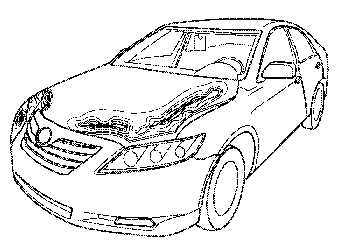
Heat map of vehicle damage
a heat map and vehicle technology, applied in the field of image processing system and technique, can solve the problems of no known image processing system that can known image processing systems are unable to quickly and effectively detect, isolate, or quantify damage that may have occurred to an automobile,
- Summary
- Abstract
- Description
- Claims
- Application Information
AI Technical Summary
Benefits of technology
Problems solved by technology
Method used
Image

Examples
Embodiment Construction
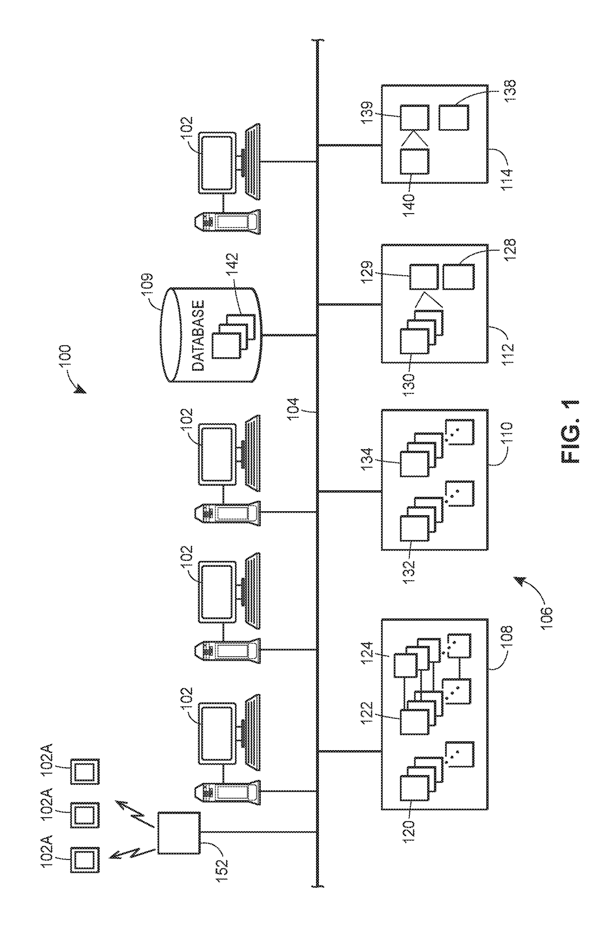
[0028]FIG. 1 illustrates one example of an image processing system 100 which may be used to determine changes to a target object, automatically or semi-automatically, generally by determining differences between one or more images of the target object as changed and one or more images generated from a base model of the object representing the object prior to the changes occurring to the object. After changes to the target object have been determined and quantified in some manner, further processing systems, which may be incorporated into the image processing system 100, may be used to determine secondary characteristics or features associated with the target object, such as the amount of change or damage to the target object (assuming that the changes to the object represent damage), costs associated with repairing or replacing the target object, the time it may take to repair the target object, the progress the target object has undergone in changing states, etc.
[0029]As illustrate...
PUM
 Abstract
Description
Claims
Application Information