Camera stabilizer

a technology for stabilizing cameras and stabilizers, applied in the field of camera accessories, can solve the problems of unsatisfactory gravity center adjustment performance, bad adaptability and portability of existing stabilizers, and limited horizontal movement, so as to improve the user's experience of operating the camera stabilizer, facilitate and easy adjustment of gravity center, and quick balance of gravity center

Inactive Publication Date: 2018-02-13
GUILIN FEIYU TECH CORP LTD
View PDF5 Cites 17 Cited by
  • Summary
  • Abstract
  • Description
  • Claims
  • Application Information

AI Technical Summary

Benefits of technology

[0019]The present invention provides a camera stabilizer comprising a mounting assembly and a gravity center adjusting assembly arranged below the mounting assembly, allowing convenient and easy adjustment of gravity center of the photography equipment by means of the longitudinal adjusting mechanism and the transverse adjusting mechanism, enabling quick balance of the gravity center of the whole camera stabilizer by the counterweight balancing mechanism in combination with the adjusting rod mechanism, and improving the users' experience of operating the camera stabilizer and improving efficiency as well.

Problems solved by technology

Most support assemblies available in the market are in fixed size and only photography equipment with specific sizes can be attached, which lead to bad adaptability and portability.
Some supporting assemblies offer supports for every camera size, but their horizontal movement may be limited.
In conclusion, the existing stabilizers have bad adaptability and unsatisfactory gravity center adjustment performance.

Method used


Image

  • Camera stabilizer
  • Camera stabilizer
  • Camera stabilizer

Examples


Embodiment Construction

[0028]The present invention will be further explained below in detail with reference to figures and particular embodiments. The embodiments described are to be regarded as illustrative rather than restrictive.

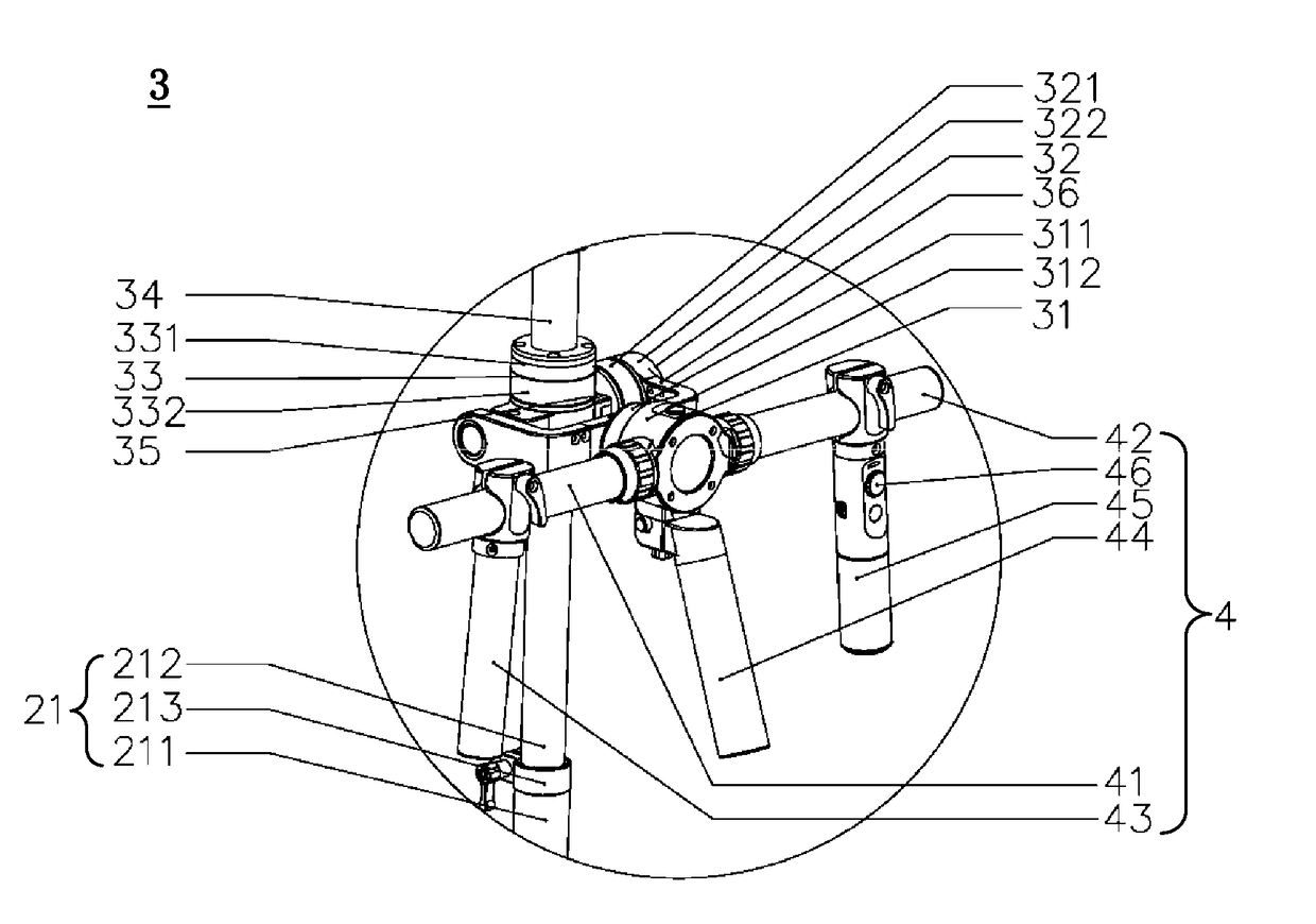
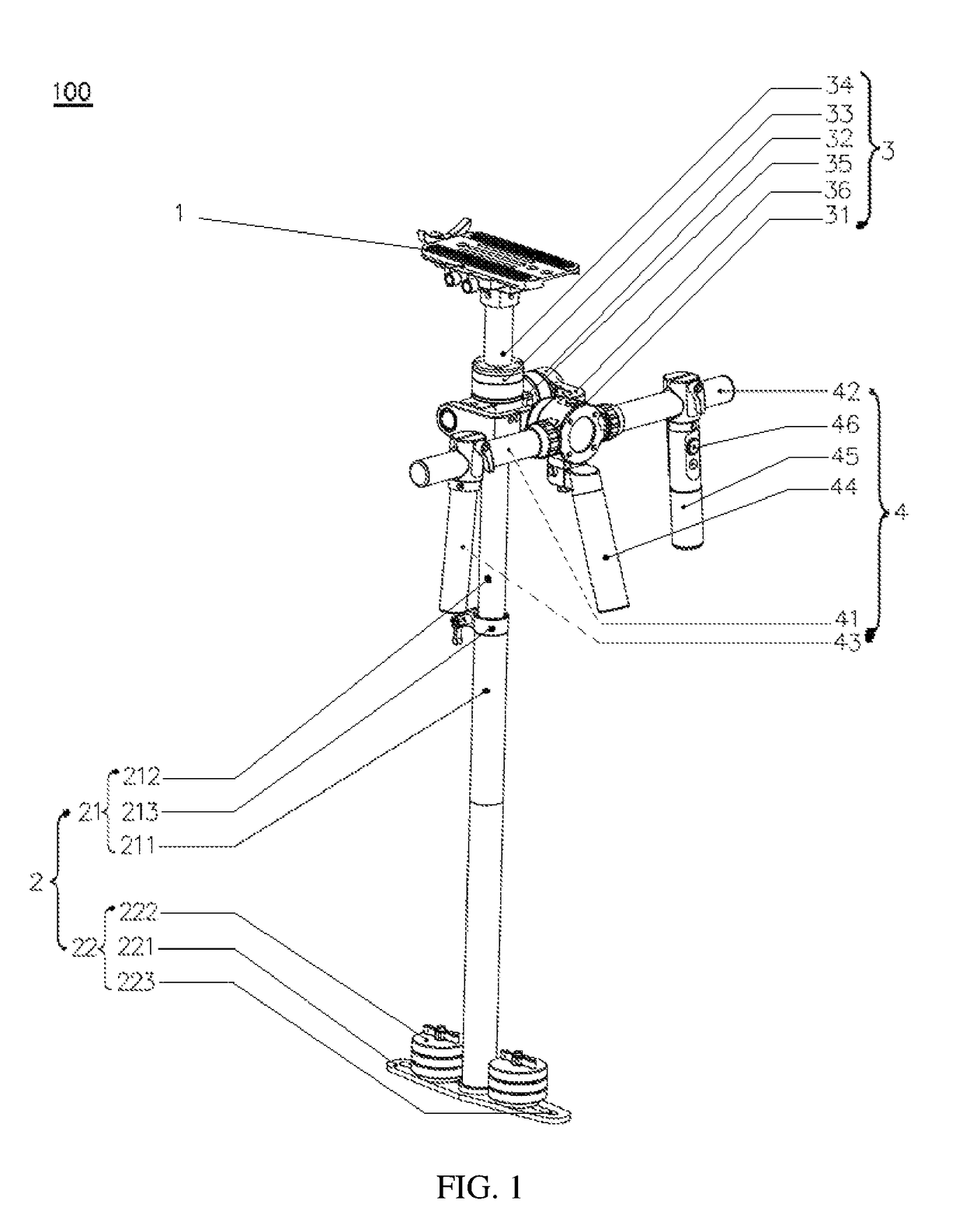
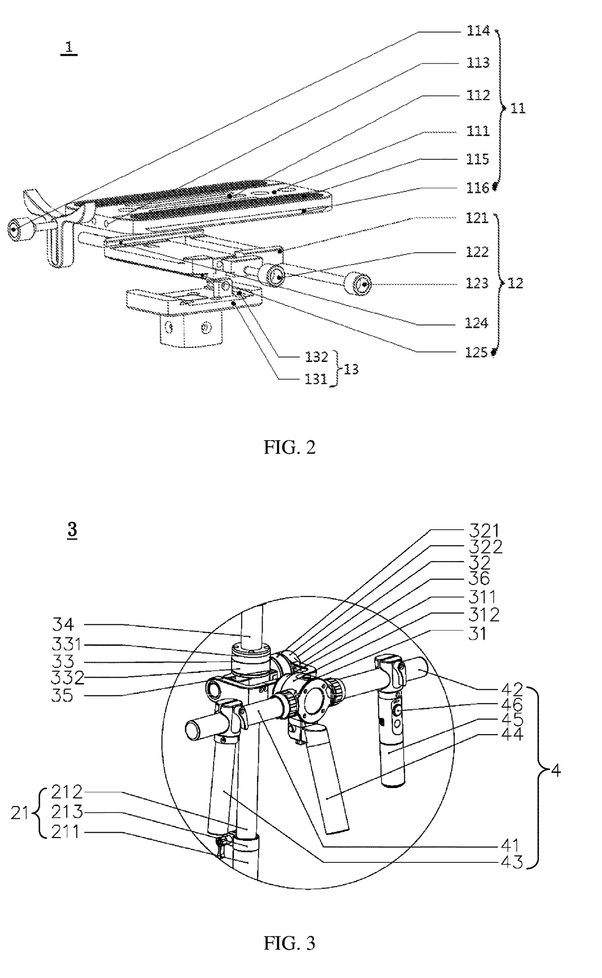
[0029]Please referring to FIG. 1, a camera stabilizer 100 according to a preferred embodiment of the present invention comprises a mounting assembly 1 and a gravity center adjusting assembly 2, wherein the mounting assembly 1 is arranged above the gravity center adjusting assembly 2.

[0030]Herein, the mounting assembly 1 comprises a mounting mechanism 11 for mounting and fixing the camera, a longitudinal adjusting mechanism 12 relative to which the mounting mechanism 11 is longitudinally slidable, and a transverse adjusting mechanism 13 relative to which the longitudinal adjusting mechanism 12 is transversely slidable; and the gravity center adjusting assembly 2 comprises an adjusting rod mechanism 21 and a counterweight balancing mechanism 22, wherein the length of the adjustin...


PUM


Abstract

A camera stabilizer, comprising a mounting assembly and a gravity center adjusting assembly arranged below the mounting assembly, wherein the mounting assembly comprises a mounting mechanism for mounting camera, a longitudinal adjusting mechanism relative to which the mounting mechanism is longitudinally slidable, and a transverse adjusting mechanism relative to which the longitudinal adjusting mechanism is transversely slidable, wherein the gravity center adjusting assembly comprises an adjusting rod mechanism and a counterweight balancing mechanism, wherein the length of the adjusting rod mechanism is adjustable, and the adjusting rod mechanism has an upper end connected to the transverse adjusting mechanism and a lower end fixedly connected to the counterweight balancing mechanism. The present invention aims to provide a camera stabilizer enabling convenient adjustment and balance of the gravity center so as to overcome the problems of inconvenient and time consuming adjustment of gravity center of existing camera stabilizers.

Description

CROSS-REFERENCE TO RELATED APPLICATION[0001]This application claims the benefit of Chinese Patent Application No. 201611044935.5 filed on Nov. 22, 2016 and Chinese Utility Model Application No. 201621266317.0 filed on Nov. 22, 2016, the entire content of which is hereby incorporated by reference.FIELD OF THE INVENTION[0002]The present invention relates to the field of camera accessories, more particularly to a camera stabilizer.BACKGROUND OF THE INVENTION[0003]The camera stabilizer is a supporting platform for photography equipment. When the photography equipment is mounted on the camera stabilizer, images can be well captured because the lens of photography equipment can be well adjusted via controlling the camera stabilizer. The application of the stabilizing stand gives camera operator freedom of motion during shooting while reducing visual artifacts in the shot due to that motion, e.g., camera vibration or shake. Overall, some common shooting errors such as crooked, fuzzy pictur...

Claims


Application Information

Patent Timeline
Patent Type & Authority Patents(United States)
IPC IPC(8): G03B17/56F16M11/04F16M13/04F16M11/08F16M11/12F16M11/18
CPCG03B17/561F16M11/048F16M11/045F16M13/04F16M11/08F16M11/12F16M11/18G03B17/563F16M2200/04F16M11/205
Inventor WEI, CHENGYUN
Owner GUILIN FEIYU TECH CORP LTD
Why Eureka
Try Eureka