Paravalvular leak sealing mechanism

a technology of paravalvular valve and sealing mechanism, which is applied in the field of paravalvular leak sealing mechanism, can solve the problems of reducing cardiac efficiency, affecting performance, and putting a greater strain on the heart muscle, and achieves the effect of improving sealing and facilitating sealing against paravalvular leakag

Active Publication Date: 2018-03-13
ST JUDE MEDICAL CARDILOGY DIV INC
View PDF603 Cites 4 Cited by
  • Summary
  • Abstract
  • Description
  • Claims
  • Application Information

AI Technical Summary

Problems solved by technology

For example, inaccurate deployment and anchoring may result in the leakage of blood between the implanted heart valve and the native valve annulus, commonly referred to as perivalvular or paravalvular leakage (“PV leak”).
In aortic valves, this leakage enables blood to flow from the aorta back into the left ventricle, reducing cardiac efficiency and putting a greater strain on the heart muscle.
Additionally, calcification of the aortic valve may affect performance and the interaction between the implanted valve and the calcified tissue is believed to be relevant to leakage.

Method used


Image

  • Paravalvular leak sealing mechanism
  • Paravalvular leak sealing mechanism
  • Paravalvular leak sealing mechanism

Examples


Embodiment Construction

[0029]As used herein, the term “proximal,” when used in connection with a prosthetic heart valve, refers to the end of the heart valve closest to the heart when the heart valve is implanted in a patient, whereas the term “distal,” when used in connection with a prosthetic heart valve, refers to the end of the heart valve farthest from the heart when the heart valve is implanted in a patient. The term “circumferential,” when used in connection with a prosthetic heart valve, refers to the direction around the perimeter of the valve. Also, when used herein, the words “generally” and “substantially” are intended to mean that slight variations from absolute are included within the scope of the structure or process recited.

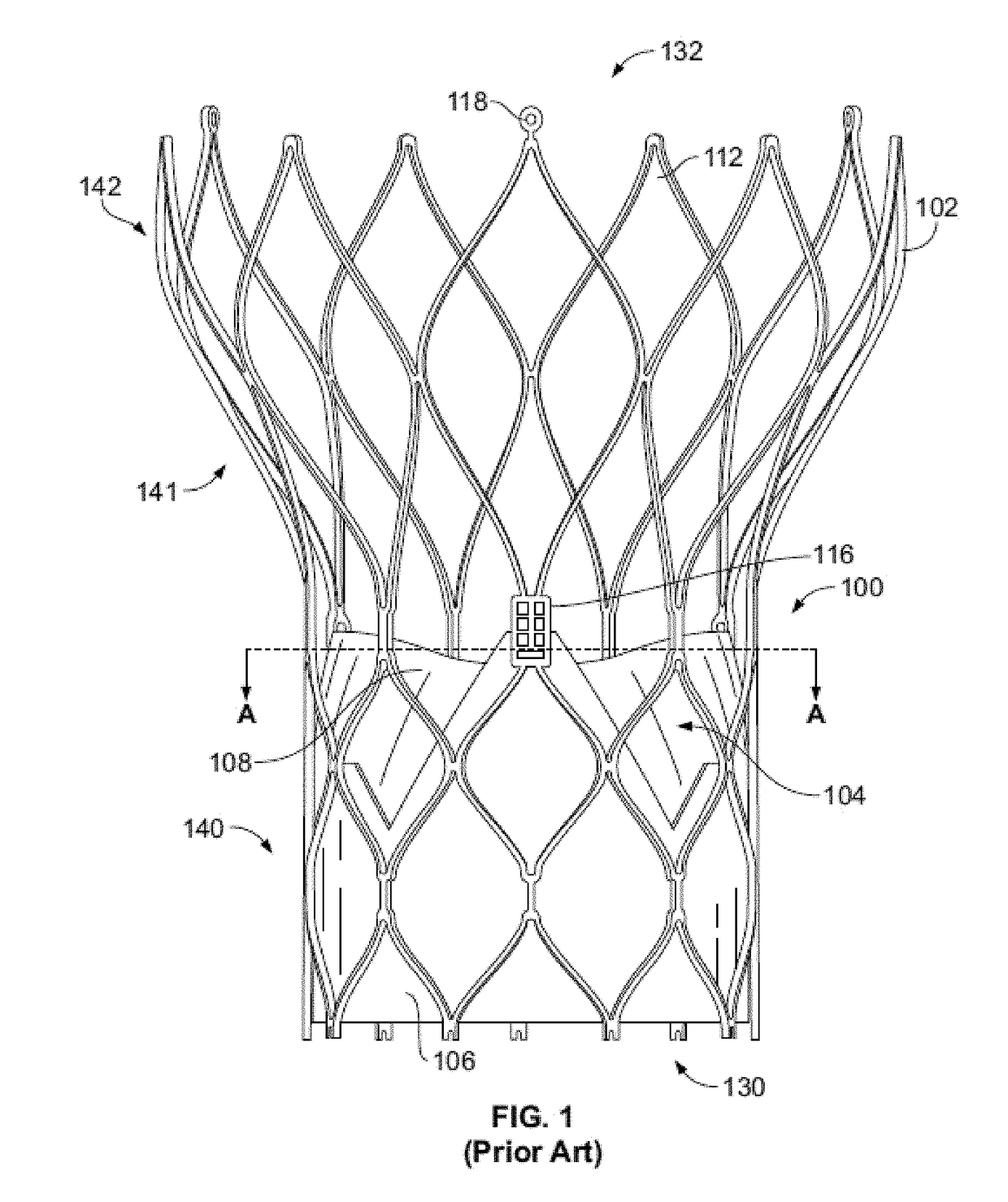
[0030]FIG. 1 shows a collapsible stent-supported prosthetic heart valve 100 known in the art. The prosthetic heart valve 100 is designed to replace the function of a native tricuspid, bicuspid or unicuspid valve of a patient, such as a native aortic valve. It should be ...


PUM


Abstract

A collapsible and expandable stent body includes a generally tubular annulus section, one or more prosthetic valve elements mounted to the stent body, and a cuff attached to the stent body. The prosthetic valve is operative to allow flow in an antegrade direction but to substantially block flow in a retrograde direction. The prosthetic heart valve may include paravalvular leak mitigation features in the form of first and second sealing members. The sealing members are attached to the cuff and extend circumferentially around an abluminal surface of the stent body. The sealing members each have an open side facing in a first axial direction and a closed side facing in an opposite second axial direction. Flow of blood in the second axial direction will tend to force blood into the sealing members and cause the sealing members to billow outwardly relative to the stent body, helping to mitigate paravalvular leak.

Description

CROSS-REFERENCE TO RELATED APPLICATIONS[0001]The present application is a continuation-in-part of U.S. patent application Ser. No. 14 / 501,200, now U.S. Pat. No. 9,668,857, filed Sep. 30, 2014, which claims the benefit of the filing date of U.S. Provisional Patent Application No. 61 / 900,475 filed Nov. 6, 2013, the disclosures of which are both hereby incorporated by reference herein.BACKGROUND[0002]The present disclosure relates to heart valve replacement and, in particular, to collapsible prosthetic heart valves. More particularly, the present disclosure relates to collapsible prosthetic heart valves having improved mechanisms to seal against paravalvular leak.[0003]Prosthetic heart valves that are collapsible to a relatively small circumferential size can be delivered into a patient less invasively than valves that are not collapsible. For example, a collapsible valve may be delivered into a patient via a tube-like delivery apparatus such as a catheter, a trocar, a laparoscopic ins...

Claims


Application Information

Patent Timeline
Patent Type & Authority Patents(United States)
IPC IPC(8): A61F2/24
CPCA61F2/2418A61F2/2409A61F2210/0061A61F2250/0069A61F2230/0013A61F2230/0023A61F2230/0026A61F2220/0075
Inventor BRAIDO, PETER N.FAHIM, MINA S.
Owner ST JUDE MEDICAL CARDILOGY DIV INC
Why Eureka
Try Eureka