
Rotation rate sensor and method for operating a rotation rate sensor

a technology of rotation rate sensor and rotation rate, which is applied in the direction of speed measurement using gyroscopic effects, instruments, surveying and navigation, etc., can solve the problems of non-linear dependence and unknown, and achieve the effect of improving signal quality

Active Publication Date: 2018-03-13
ROBERT BOSCH GMBH
View PDF3 Cites 0 Cited by
  • Summary
  • Abstract
  • Description
  • Claims
  • Application Information

AI Technical Summary

Benefits of technology

The present invention provides a rotation rate sensor and method of operating it that is capable of compensating for a non-linear dependence of the 2 f quadrature force, which is a force that affects the detection of rotation. This is achieved through the use of a compensation element that exerts a non-linear dependence on the deflection in the excitation direction. Additionally, the rotation rate sensor includes a Coriolis element which facilitates optimum modulation of the sensor. The technical effect of this invention is improved signal quality and more accurate detection of rotation.

Problems solved by technology

However, structures for compensating the 2 f quadrature force which have a non-linear dependence of the compensation force on the excitation oscillation are not known yet.

Method used


Image

  • Rotation rate sensor and method for operating a rotation rate sensor
  • Rotation rate sensor and method for operating a rotation rate sensor
  • Rotation rate sensor and method for operating a rotation rate sensor

Examples


Embodiment Construction

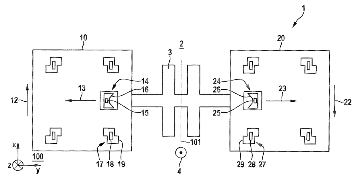
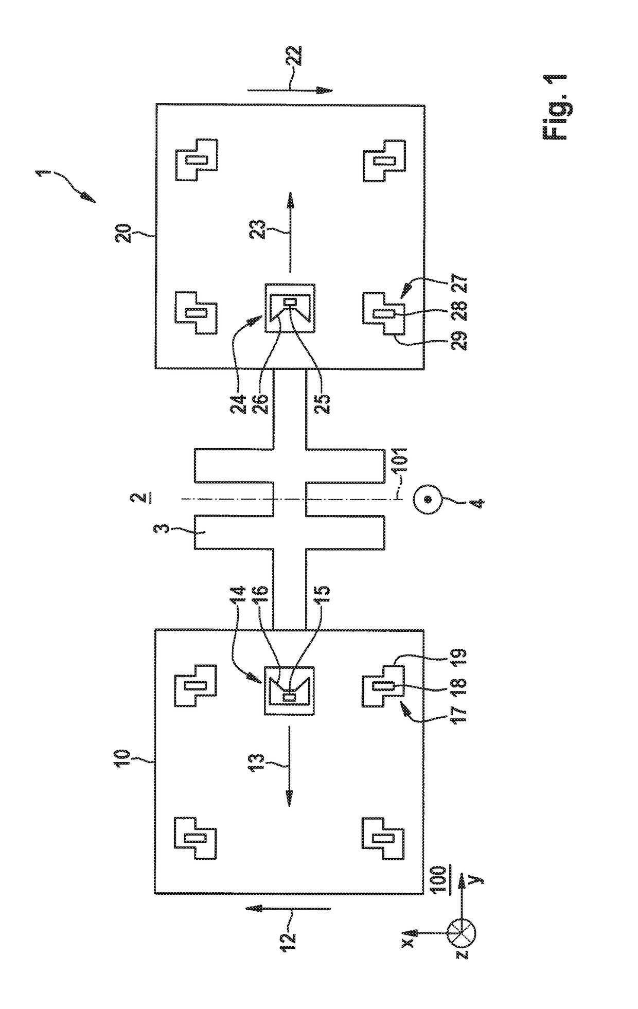
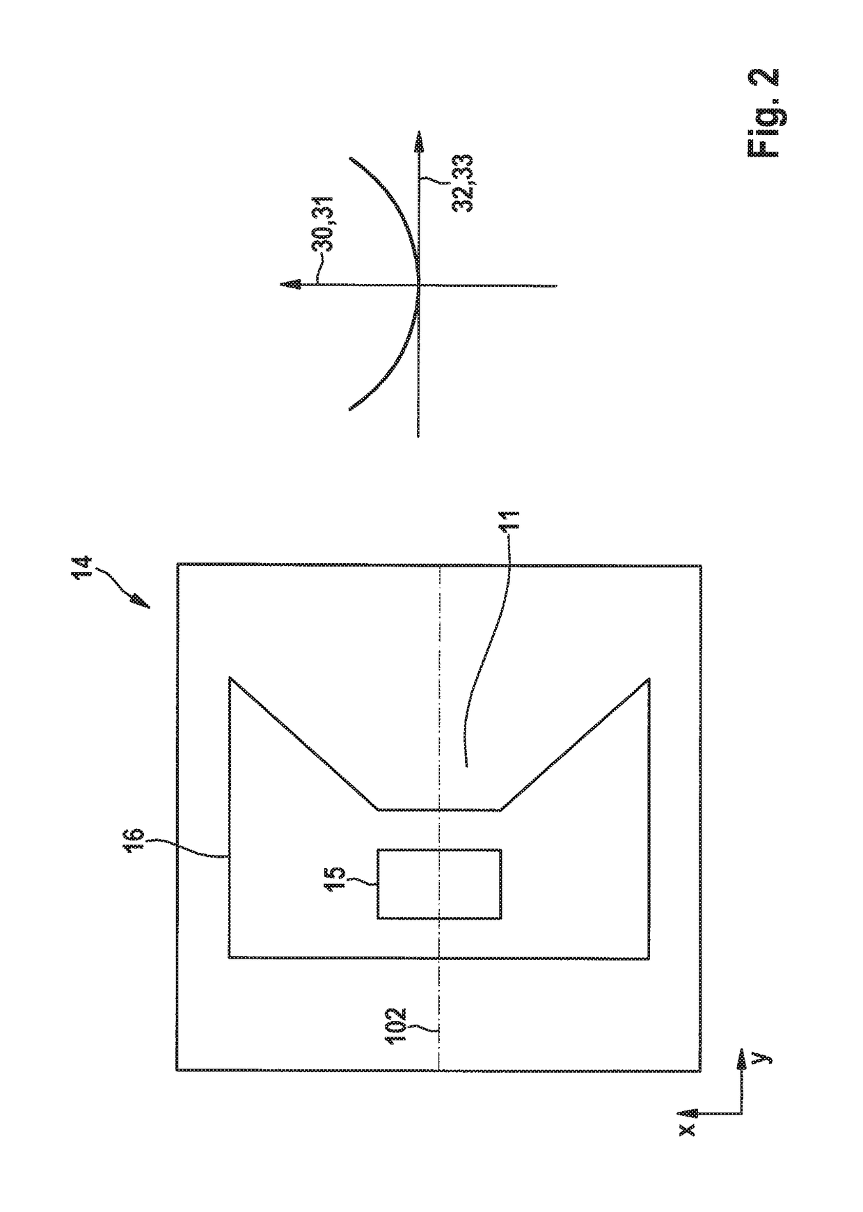
[0018]FIG. 1 schematically shows a top view onto a rotation rate sensor 1 according to one exemplary specific embodiment of the present invention. Rotation rate sensor 1 includes a substrate 2 having a main extension plane 100, a Coriolis element 10, and a further Coriolis element 20. Coriolis element 10 is coupled via a spring element 3 to further Coriolis element 20. Moreover, Coriolis element 10 is excitable with the aid of an excitation arrangement, which is not shown, to carry out an excitation oscillation 12 along an excitation direction which extends along a first direction X in parallel to main extension plane 100. As a result, Coriolis element 10 experiences a deflection 33 in the excitation direction, as shown on the right side of FIG. 2. Further Coriolis element 20 is excitable with the aid of a further excitation arrangement, which is not shown, to carry out a further excitation oscillation 22 antiparallel to excitation oscillation 12.

[0019]In the case of a rotation rate...


PUM


Abstract

A rotation rate sensor includes a substrate having a main extension plane and a Coriolis element, in which the rotation rate sensor is configured so that the Coriolis element is excitable with the aid of an excitation arrangement to carry out an excitation oscillation along a first direction and in parallel to the main extension plane, the rotation rate sensor including a compensation element for exerting a compensation force, the compensation force having a non-linear dependence on the excitation oscillation.

Description

RELATED APPLICATION INFORMATION[0001]The present application claims priority to and the benefit of German patent application no. 10 2015 201 544.0, which was filed in Germany on Jan. 29, 2015, the disclosure of which is incorporated herein by reference.FIELD OF THE INVENTION[0002]The present invention is directed to a rotation rate sensor.BACKGROUND INFORMATION[0003]Such rotation rate sensors are believed to be generally understood. Such rotation rate sensors include a substrate having a main extension plane and at least one Coriolis element, the Coriolis element being excitable with the aid of an excitation arrangement to carry out an excitation oscillation along an excitation direction which extends along a first direction in parallel to the main extension plane, whereby the Coriolis element experiences a deflection in the excitation direction. In the case of a rotational movement, a detection signal is detected as a function of a force action on the Coriolis element which is to b...

Claims


Application Information

Patent Timeline
Patent Type & Authority Patents(United States)
IPC IPC(8): G01C19/574
CPCG01C19/574B81B7/0009G01C19/5733
Inventor PRUETZ, ODD-AXELZEHRINGER, STEFAN
Owner ROBERT BOSCH GMBH
Learn More