End structure of nozzle, purging device, and load port

a technology of end structure and nozzle, which is applied in the direction of basic electric elements, semiconductor/solid-state device manufacturing, electric devices, etc., can solve the problems of troublesome necessity of changing the nozzle and inability to deal with the situation

Active Publication Date: 2018-03-13
SINFONIA TECHNOLOGY CO LTD
View PDF13 Cites 6 Cited by
  • Summary
  • Abstract
  • Description
  • Claims
  • Application Information

AI Technical Summary

Benefits of technology

[0006]For grommet type FOUPs, nozzles each having a lip-shaped protruding portion provided at its upper end portion are used, as described in Patent Literature 1, to establish good and close contact between the nozzles and the corresponding grommets, for preventing gas leakage during purging. Meanwhile, for lip type FOUPs, nozzles each having a portion made of relatively soft material is provided at its upper end portion, to establish good and close contact between the nozzles and the corresponding lip members.
[0012]The protruding portion is generally formed integrally with a nozzle main body made of metal. Meanwhile, the flat portion is formed by a rubber member or the like which is softer than the nozzle main body and which is placed on an upper surface of the nozzle main body. Due to this structure, there is a possibility that a gap is created an under surface of the flat portion and the upper surface of the nozzle main body, and this gap may function as a path of gas leakage. Thus, as described above, the protruding portion is provided between the gas-flow passage and the flat portion. The protruding portion prevents gas from reaching the gap, to reliably prevent gas leakage.
[0014]As described above, the flat portion is made of relatively soft material such as rubber, and therefore the flat portion is more likely to be damaged by contact with another member, for example. Thus, by providing the protruding portion outside the flat portion, the soft flat portion is protected by the protruding portion. Thereby, damage to the flat portion is prevented.
[0017]The above-described purging device and the load port enable suitable purging of both of the grommet type containers and the lip type containers without the need of replacing the nozzle.

Problems solved by technology

Thus, there has been troublesome necessity of changing nozzles with the change of the type of the container used.
Further, because different nozzles have been used for the grommet type containers and the lip type containers, it has been impossible to deal with the situation where the grommet type and lip type containers are used in a mixed manner.

Method used


Image

  • End structure of nozzle, purging device, and load port
  • End structure of nozzle, purging device, and load port
  • End structure of nozzle, purging device, and load port

Examples


Embodiment Construction

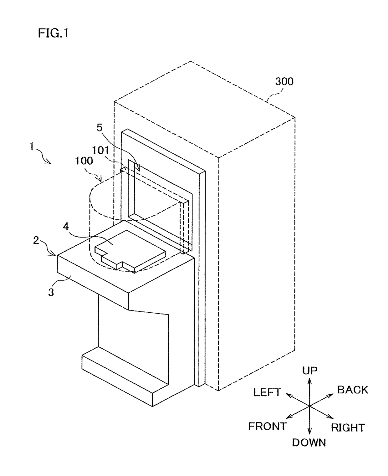
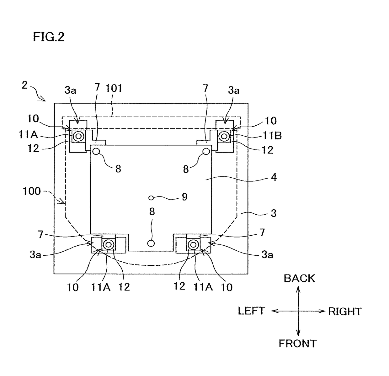
[0027]The following will describe an embodiment of the present invention with reference to the drawings. FIG. 1 is a perspective view of a load port of this embodiment. FIG. 2 is a top view of a table of the load port. The following description will be given referring to directions indicated in the drawings, as needed.

[0028]A load port 1 of this embodiment is configured to purge a FOUP 100 functioning as a container. The FOUP 100 is configured to contain a plurality of not-illustrated wafers functioning as objects to be contained. The load port 1 is provided adjacent to a semiconductor manufacturing device 300. The load port 1 includes a table 2 configured so that the FOUP 100 is placed thereon. The table 2 includes a base housing 3, and a plate-like carrier base 4 provided on the base housing 3. The FOUP 100 is placed on the carrier base 4 of the table 2.

[0029]The load port 1 has a passage opening 5 configured to allow the wafers to pass therethrough. In the state where the FOUP 10...


PUM


Abstract

There is provided an end structure of a nozzle (11) including a gas-flow passage (13) communicable with an opening (104) provided through a bottom of a container (100) configured to contain an object, the nozzle (11) configured so that gas is injected into or discharged from the container (100) through the gas-flow passage (13) and the opening (104). The end structure includes a contact portion (19) provided at an upper end portion of the nozzle (11) and around the gas-flow passage (13), and the contact portion (19) is configured to be brought into contact with a contacted portion (103) provided around the opening (104). The contact portion (19) includes a flat portion (19b) and protruding portions (19a and 19c) each protruding upward relative to the flat portion (19b), and the flat portion (19b) is made of material softer than that of the protruding portions (19a and 19c).

Description

CROSS REFERENCE TO RELATED APPLICATION[0001]The present application claims priority from Japanese Patent Application No. 2015-057368, which was filed on Mar. 20, 2015, the disclosure of which is herein incorporated by reference in its entirety.BACKGROUND OF THE INVENTION[0002]The present invention relates to: an end structure of a nozzle configured so that gas is injected into or discharged from a container containing an object; and a purging device and a load port each including a nozzle unit having the end structure.[0003]There are containers such as a FOUP (front-opening unified pod) configured to contain wafers which are material for semiconductor devices. The internal space of such a container is purged with inert gas such as nitrogen gas to prevent contamination of wafers. For example, referring to an apparatus described in Patent Literature 1 (Japanese Unexamined Patent Publication No. 2011-187539), nozzles each having a gas-flow passage are brought into contact with the bott...

Claims


Application Information

Patent Timeline
Patent Type & Authority Patents(United States)
IPC IPC(8): H01L21/67H01L21/673
CPCH01L21/67393
Inventor MORIHANA, TOSHIMITSUMATSUMOTO, YUKINATSUME, MITSUO
Owner SINFONIA TECHNOLOGY CO LTD
Why Eureka
Try Eureka