Fuel cell

Inactive Publication Date: 2005-09-01
MITSUBISHI ELECTRIC CORP
View PDF5 Cites 17 Cited by
  • Summary
  • Abstract
  • Description
  • Claims
  • Application Information

AI Technical Summary

Benefits of technology

[0008] The present invention is directed at solving the problems of the conventional fuel cells as described above, and has as an

Problems solved by technology

In this type of fuel cell, the gas diffusion layers smoothly transfer reaction gases (the fuel gas and the oxidizing gas) from the gas flow paths to the catalytic layers, and while having a function to discharge reaction-generated products, such as generated gas and water, to the gas flow paths, at the same time form slippage paths for the reaction gases, when the cell is viewed on the flat, causing a decrease in gas usage efficiency.
However, in the above described conventional fuel cel

Method used


Image

  • Fuel cell
  • Fuel cell
  • Fuel cell

Examples


embodiment 1

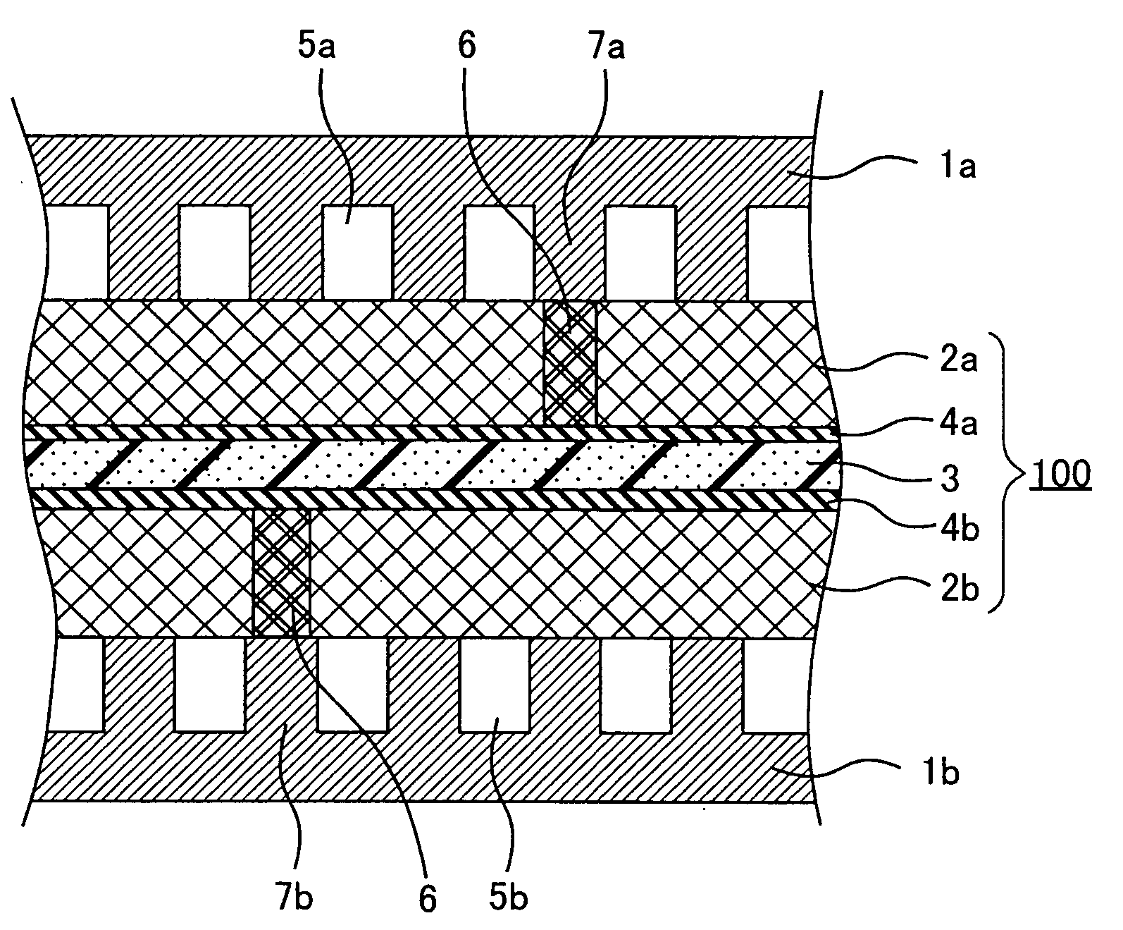
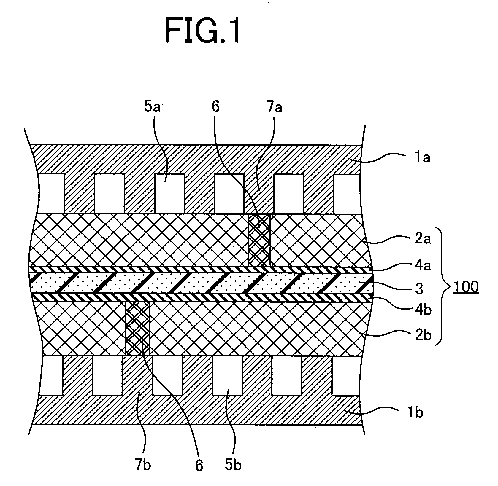
[0021]FIG. 1FIG. 4 are explanatory views of a fuel cell according to Embodiment 1 of the present invention, and more specifically, FIG. 1 is a sectional view illustrating the simulated appearance of the main members of the fuel cell cut along its stack-layer direction, FIG. 2 is a plan view of an anode gas diffusion layer and an anode-side separator viewed from an anode catalytic layer side, FIG. 3 is a plan view illustrating an enlargement of a portion of FIG. 2, and FIG. 4 is a plan view of the anode gas diffusion layer and the anode-side separator viewed from the anode catalytic layer side.

[0022] As illustrated in FIG. 1, the present embodiment is configured as a seven-layered laminated structure unit built up of, in order, an anode-side (fuel electrode side) separator plate la, an anode gas diffusion layer 2a, an anode catalytic layer 4a, a proton-exchange electrolyte membrane 3, a cathode (oxidizing electrode) catalytic layer 4b, a cathode gas diffusion layer 2b and a cathode-...

embodiment 2

[0060]FIG. 5 is an explanatory plan view of the fuel cell according to Embodiment 2 of the present invention, and more specifically, illustrates the anode gas diffusion layer and the anode-side separator plate viewed from the anode catalytic layer side.

[0061] As illustrated in FIG. 5, the fuel cell according to this embodiment has a plurality of flow channel groups (there are three of them in FIG. 5) in which at least one of either the fuel gas flow path or the oxidizing gas flow path (in FIG. 5, the fuel gas flow path) is configured from a plurality of flow channels 5a (in FIG. 5, six flow channels), and a gas supply manifold (a fuel gas inlet manifold) 8a and a gas discharge manifold (a fuel gas outlet manifold) 8b with which the flow channels 5a commonly communicate, and it is configured so that the gas in neighboring flow channel groups flows in opposing directions.

[0062] Furthermore, among the ridges between the neighboring flow channel groups, resin is impregnated into the h...

embodiment 3

[0070]FIG. 6 is an explanatory plan view of the fuel cell according to Embodiment 3 of the present invention, and more specifically, illustrates the anode gas diffusion layer and the anode-side separator plate viewed from the anode catalytic layer side.

[0071] As illustrated in FIG. 6, the fuel cell according to this embodiment has a plurality of flow channel groups (there are three of them in FIG. 6) in which at least one of either the fuel gas flow path or the oxidizing gas flow path (although only the fuel gas flow path is illustrated in FIG. 6, both flow paths are present in this embodiment) is configured from the flow channels that run in bends (in FIG. 6, three flow channels) and a gas supply manifold (a fuel gas inlet manifold) 8a and a gas discharge manifold (a fuel gas outlet manifold) 8b with which the flow channels commonly communicate, and it is configured so that the gas in neighboring flow channel groups flows in similar directions.

[0072] Furthermore, resin is impregn...


PUM


Abstract

A fuel cell that prevents gas slippage, with minimal reduction in effective area for electrode reaction. At least one of a fuel gas flow path and an oxidizing gas flow path is configured with flow channels having bends and so that gas flows between ends of the flow channels, and, among ridges between a neighboring upstream-side portion of a flow channel and a downstream-side portion of the flow channel, a gas diffusion layer touching at least a ridge between an upstream region of the flow channel on the upstream side and a downstream region of the flow channel on the downstream side, has a lower porosity than the gas diffusion layer touching other ridges and touching the flow channels.

Description

BACKGROUND OF THE INVENTION [0001] 1. Field of the Invention [0002] The present invention relates to fuel cells using an electrochemical reaction, and in particular, to the prevention of slippage of gas flowing in flow paths. [0003] 2. Description of the Related Art [0004] In general, fuel cells comprise: an electrochemical electro-chemical electricity-generating element that sandwiches and holds an ion-conducting electrolyte membrane, via porous catalytic layers, between a fuel electrode and an oxidizing electrode that include the catalytic layers and porous gas diffusion layers; a first separator plate, disposed on one side of the electrochemical electricity-generating element, on which is arranged a fuel gas flow path for supplying fuel gas for the fuel electrode, and a second separator plate, disposed on the other side of the electrochemical electricity-generating element, on which is arranged an oxidizing gas flow path for supplying oxidizing gas for the oxidizing electrode. [0...

Claims


Application Information

Patent Timeline
IPC IPC(8): H01M4/86H01M4/88H01M8/02H01M4/94H01M8/00H01M8/04H01M8/10H01M8/24
CPCH01M4/8605H01M8/023Y02E60/50H01M8/04089H01M8/241H01M8/0258H01M8/2483H01M8/0267H01M8/0263
Inventor YOSHIOKA, SHOJIOKADA, TATSUNORIHIROI, OSAMU
Owner MITSUBISHI ELECTRIC CORP
Why Eureka
Try Eureka