Controlling pressure

a technology of controlling pressure and pressure, applied in the field of controlling pressure, can solve the problems of difficult fluid handling, inability to accurately recapture the structure, function, physiology of living tissues in vivo, and often questionable physiological relevance of in vitro data to in vivo systems

Active Publication Date: 2017-03-02
EMULATE INC
View PDF0 Cites 19 Cited by
  • Summary
  • Abstract
  • Description
  • Claims
  • Application Information

AI Technical Summary

Benefits of technology

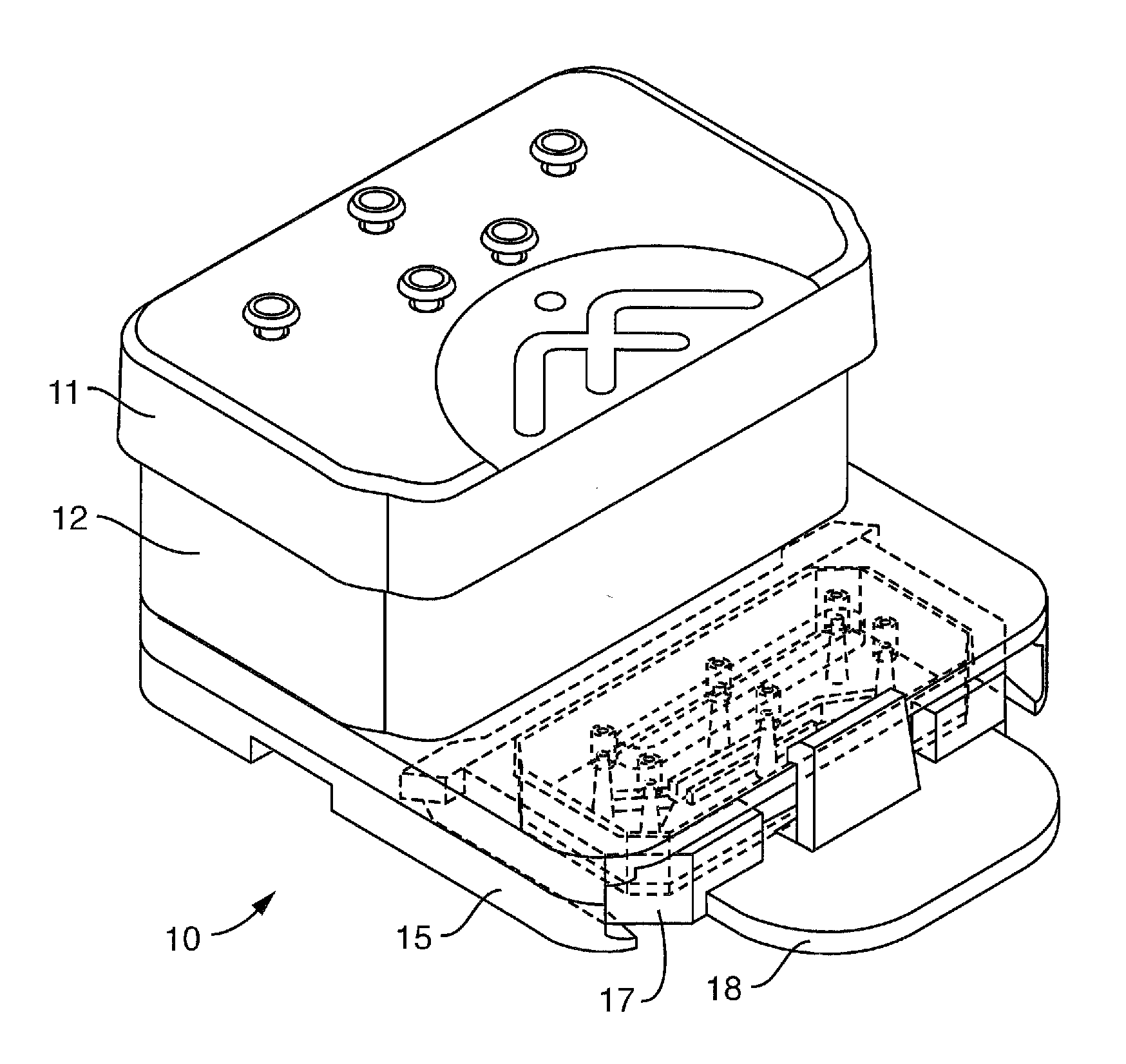
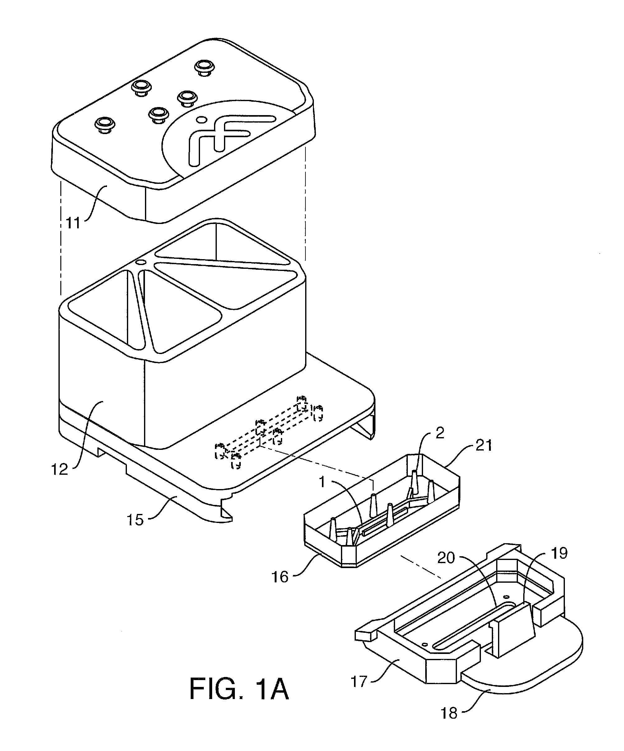
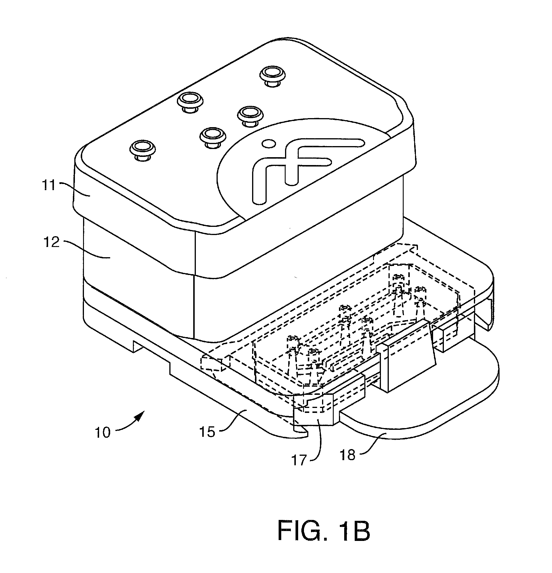
[0007]A culture module is contemplated that allows the perfusion and optionally mechanical actuation of one or more microfluidic devices, such as organ-on-a-chip microfluidic devices comprising cells that mimic at least one function of an organ in the body. In one embodiment, the microfluidic device comprises a top channel, a bottom channel, and a membrane separating at least a portion of said top and bottom channels. In one embodiment, the microfluidic device comprises cells on the membrane and / or in or on the channels. In one embodiment, the culture module comprises a pressure manifold that allows for perfusion of a microfluidic device, such as an “organ on chip” microfluidic device comprising cells that mimic cells in an organ in the body or at least one function of an organ, that is optionally retained in contact with a perfusion disposable and detachably linked with said assembly so that fluid enters ports of the microfluidic device from a fluid reservoir, optionally without tubing, at a controllable flow rate. The perfusion disposable can be used separately from the culture module, and the microfluidic device or chip can be used separately from the perfusion disposable. In one embodiment, the present invention contemplates a (moving or non-moving) pressure manifold configured to mate with one or more microfluidic devices (such as any one of the perfusion manifold assembly embodiments described herein) with integrated valves that can prevent gas leaks when not mated with a microfluidic device.

Problems solved by technology

Although such 2D in vitro models are less expensive than animal models and are conducive to systematic, and reproducible quantitative studies of cell physiology (e.g., in drug discovery and development), the physiological relevance of the information retrieved from in vitro studies to in vivo system is often questionable.
Said another way, 2D cell culture systems do not accurately recapitulate the structure, function, physiology of living tissues in vivo.
While such microfluidic devices are an improvement over traditional static tissue culture models, the small size, scale and interface of these devices makes fluid handling difficult.

Method used


Image

  • Controlling pressure
  • Controlling pressure
  • Controlling pressure

Examples


example 1

[0242]Conditions for bonding the capping layer (FIG. 2A-2E-2, element 13) to the backplane (14) were examined. Extruded SEBS sheets were bonded to a hot embossed plate. The SEBS sheets were designed to act as the capping layer to the channels that are formed in the COP via the hot embossing process and as a fluid and gas gasketing to mating parts. The testing showed that the 1 mm thick SEBS was better as a fluid seal between the reservoirs and the backplane. The hot embossed plates were fabricated from Zeonor 1420R. The SEBS materials used were:

[0243]A. Thickness: 1 mm, Material: Kraton G1643, Mfg Process: extrusion

[0244]B. Thickness: 0.2 mm, Material: Kraton G1643+5% Polypropylene, Mfg Process: extrusion

An oven process was used in comparison to a laminator. The laminator produced marginal to not adequate bonding. However, the oven process revealed the following:

Material Thickness0.2 mm SEBS1 mm SEBSBonding Temp (C.)8080Bonding Time1 hr-24 hrClamping PressureNone0.5 kgApplied throug...

example 2

[0246]In this example, one embodiment of a protocol for chip activation is discussed. The example assumes that all work is done under a hood using aseptic techniques and all working spaces are sterile (or made sterile).

[0247]Part I: Preparing the Chip

A. Spray the exterior of the chip package with 70% Ethanol and wipe it prior to bring it inside hood.

B. Open package inside hood and take chip in chip carrier out (keep these together).

C. Place chip in chip carrier within large sterile dish

i. Only handle the chip carriers by their wings. Always use tweezer to handle chip, The surface of chip is connected with cell culture area. Avoid touching the surface of the chip with hands and keep the chip unit flat

D. Allow vial of Emulate Reagent 1 (ER1) powder (containing a cross-linker) to fully equilibrate to ambient temperature before opening to prevent condensation inside the storage container—ER1 is moisture and light sensitive

E. Turn the light in the biosafety hood off

F. Reconstitute the po...

example 3

[0250]This example provides one embodiment of a protocol for seeding cells inside the chip in the top channel (which is oriented horizontally, unless otherwise indicated). The example assumes aseptic techniques and a sterile environment.

[0251]It should be noted that, although some cells require very specific seeding conditions, in general an optimal seeding density is achieved when the cells are in a planar monolayer spaced closely. From this spacing, most primary cells will attach and spread into a confluent monolayer. Reference is made below to “gravity washing.” This involves a) placing a (bolus) drop of media (100 uL) over a port on one side of the channel, making sure not to introduce any air bubbles within the port itself, and b) allowing this to flow through the chip, constantly aspirating media excess from the outlet port.

A. Transfer the chips into the hood

B. Place them inside of a sterile dish (eg 15 mm culture dish)

C. Gently wash chips

i. Pipette up 200 ul of cell culture m...


PUM

PropertyMeasurementUnit
average gas pressureaaaaaaaaaa
pressureaaaaaaaaaa
contact anglesaaaaaaaaaa

Abstract

A culture module is contemplated that allows the perfusion and optionally mechanical actuation of one or more microfluidic devices, such as organ-on-a-chip microfluidic devices comprising cells that mimic at least one function of an organ in the body. A method for pressure control is contemplated to allow the control of flow rate (while perfusing cells) despite limitations of common pressure regulators. The method for pressure control allows for perfusion of a microfluidic device, such as an organ on a chip microfluidic device comprising cells that mimic cells in an organ in the body, that is detachably linked with said assembly, so that fluid enters ports of the microfluidic device from a fluid reservoir, optionally without tubing, at a controllable flow rate.

Description

FIELD OF THE INVENTION[0001]A perfusion manifold assembly is contemplated that allows for perfusion of a microfluidic device, such as an organ on a chip microfluidic device comprising cells that mimic cells in an organ in the body or at least one function of an organ, that is detachably linked with said assembly so that fluid enters ports of the microfluidic device from a fluid reservoir, optionally without tubing, at a controllable flow rate. A drop-to-drop connection scheme is contemplated as one embodiment for putting a microfluidic device in fluidic communication with a fluid source or another microfluidic device, including but not limited to, putting a microfluidic device in fluidic communication with the perfusion manifold assembly.BACKGROUND OF THE INVENTION[0002]Two-dimensional (2D) monolayer cell culture systems have been used for many years in biological research. The most common cell culture platform is the two-dimensional (2D) monolayer cell culture in petri dishes or fl...

Claims


Application Information

Patent Timeline
Patent Type & Authority Applications(United States)
IPC IPC(8): C12N5/071C12M1/42C12M1/34C12M3/06C12M1/00
CPCC12N5/0602C12M23/16C12N2521/00C12M41/40C12M35/04C12M29/10C12M23/38C12M23/40C12M23/42C12M37/04C12M41/48B01L3/5027B01L3/502707B01L3/502715B01L3/502723B01L3/50273B01L3/502738B01L3/567B01L9/527A01N1/0247A01N1/021B01L2200/025B01L2200/027B01L2200/12B01L2300/049B01L2300/0681B01L2300/0887B01L2300/123B01L2300/14B01L2300/161B01L2300/165B01L2400/0481B01L2400/0487B01L2400/06C12M21/08C12M23/44
Inventor LEVNER, DANIELSLIZ, JOSIAH DANIELHINOJOSA, CHRISTOPHER DAVIDGOMES, JOSHUAFERNANDEZ-ALCON, JOSA
Owner EMULATE INC
Why Eureka
Try Eureka