System for isolating power conductors using molded assemblies

a technology of power conductors and molded assemblies, applied in the field of electric systems, can solve the problems of mcc and/or constituent components of mcc access and/or dimension constraints, and achieve the effects of long cycle time and energy consumption, large energy consumption, and long lead tim

Active Publication Date: 2018-03-13
ROCKWELL AUTOMATION TECH
View PDF6 Cites 6 Cited by
  • Summary
  • Abstract
  • Description
  • Claims
  • Application Information

AI Technical Summary

Benefits of technology

[0008]Aspects of the invention may allow for insulation of a back side of an isolated bus support without the need to modify the isolated bus support. This overcomes the significant challenges and lead-times encountered with having to use epoxy to insulate such areas. The invention may be part of a system for insulating buses, such as in compliance with the International Electrotechnical Commission (IEC) 61641:2014 guide for testing under conditions of arcing due to internal fault. Accordingly, a molded insulator may be provided instead of less desirable epoxy, molded boots, shrink tubing and / or tape. The invention may provide a molded insulator with contours which may work with virtually any bus geometry.
[0009]A fastener, bus clamp or other power conductor may be “live” if it carries electrical current or charge, such as by going through a current carrying bus for structural mounting and / or current exchange. The electrically insulating molded assembly may also protect against such exposed live fasteners.
[0010]Aspects of the invention may eliminate the need to modify the isolated bus support molding; may avoid requiring a re-test of any short circuit as the structural support of the bus may remain unchanged; and may be backwards compatible with systems already deployed in the field. Aspects of the invention may also avoid shrink tubing, which may require rounded edge bus bars and an oven with process controls to shrink uniformly (further requiring long cycle times and energy consumption). Aspects of the invention may also avoid epoxy, which may be costly, have long lead times, consume large amounts of energy in track ovens to coat and cure, and which might not work with multiple bus bars for higher current ratings.
[0011]Aspects of the invention may use an injection molded part designed to create a labyrinth of insulation around a horizontal bus bar without the need for tooling modifications of an isolated bus support, or a width of a standard bus bar. The invention may advantageously avoid “doubling up” on bus bar as a full 4″ width bus can be used as procured without modifications. Accordingly, assembly time may be reduced from as much as 40 hours per section / column to as little as 2 hours or less. Also, the invention may avoid the need to manually apply heat shrink tubing to bus bars (as bus bars may typically generate significant heat), or the need to manually cut pieces of heat shrink tubing after shrinking, such as to allow conductors to be bolted together at current exchange joints. Accordingly, the invention may remove a dependency on assembly to remove shrink tubing after applying shrink tubing, and before assembly. Moreover, shrink tubing and tape may be eliminated from use in this area altogether when employing aspects of the invention.
[0012]The electrically insulating molded assembly may be a single injection molded part, may be manufactured from a thermoplastic or thermosetting polymer, and / or may be black in color to maximize radiant cooling.

Problems solved by technology

Accomplishing this within the access and / or dimension constraints of the MCC and / or constituent components of the MCC is particularly challenging.

Method used


Image

  • System for isolating power conductors using molded assemblies
  • System for isolating power conductors using molded assemblies
  • System for isolating power conductors using molded assemblies

Examples


Embodiment Construction

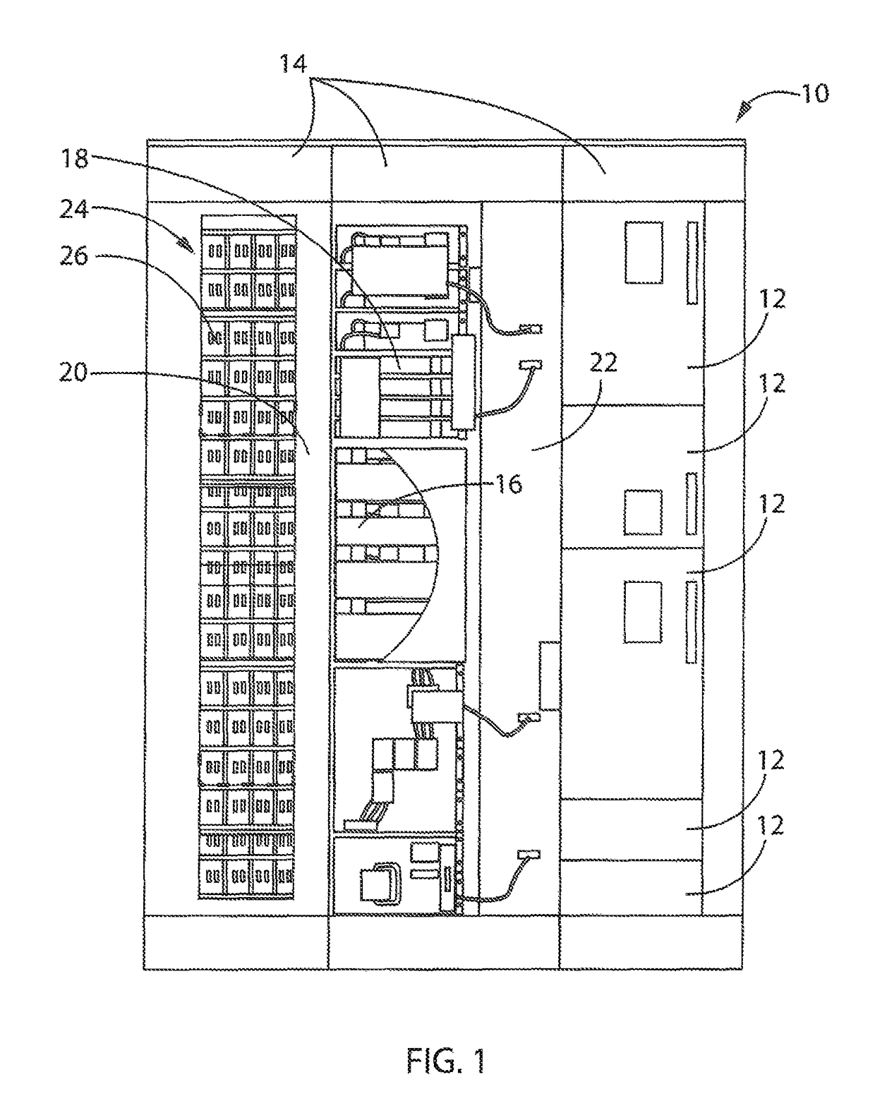
[0032]Referring now to FIG. 1, an exemplar electrical system 10 is provided in which electrical units 12 of various types may be housed. The electrical system 10 may be, for example, a Motor Control Center (“MCC”) or other industrial, commercial, marine, or other electrical system. In general, the electrical system 10 may provide one or more sections 14, each forming a shell around a device mounting volume for supporting the units 12. The shell may be made of any suitable material, such as heavy gage sheet metal, reinforced plastics, and so forth. The electrical system 10 may typically receive three-phase power from an external power supply, such as a power supply grid, and / or data signals, via appropriate conduits (not shown), and distribute the received power and / or data signals to one or more of the sections 14 in various manners. The sections 14 may be electrically isolated from one another, or alternatively, may be electrically joined with other sections 14, such as via common ...


PUM


Abstract

An improved electrical system may be provided by electrically isolating horizontal power distribution bus bars of differing phases, disposed along a preconfigured isolated bus support molding, from one another by covering each bus bar with an electrically insulating molded assembly. The electrically insulating molded assembly has contours configured to cover a particular bus bar (with respect to another bus bar or live fastener), arranged within the constraints of the preconfigured isolated bus support molding in the electrical system (such as along the back of the isolated bus support, between the isolated bus support and a wall of the electrical system).

Description

CROSS-REFERENCE TO RELATED APPLICATIONS[0001]This application claims priority to U.S. Provisional Patent Application No. 62 / 236,382, entitled “System for Isolating Power Conductors Using Molded Assemblies,” filed on Oct. 2, 2015, which is herein incorporated by reference.FIELD OF THE INVENTION[0002]The present invention relates generally to electrical systems, such as for the distribution of power signals to controlled equipment, and more particularly, to electrical isolation in such systems.BACKGROUND OF THE INVENTION[0003]Electrical systems with packaged electrical and electronic components are known and are in use. For example, Motor Control Centers (MCC's) are used for power and data distribution in large and industrial operations. In MCC's, a variety of components, such as switchgear, semiconductor power electronic circuits, programmable logic controllers, motor controllers, and so forth, are housed in large electrical enclosures that may be subdivided into sections or columns,...

Claims


Application Information

Patent Timeline
Patent Type & Authority Patents(United States)
IPC IPC(8): H02G5/00H02B1/14H02G5/02H02B1/21
CPCH02G5/025H02B1/14H02B1/21
Inventor SERDYNSKI, DAVID P.MEYER, DEAN T.
Owner ROCKWELL AUTOMATION TECH
Why Eureka
Try Eureka