Hinged input device

a technology of input device and hinge, which is applied in the field of electronic devices, can solve the problems of increasing the cost and complexity of the device, and the possibility of spring and/or hinge failure, and achieves the effect of wide range of user interface functionality and flexibility

Active Publication Date: 2018-03-20
SYNAPTICS INC
View PDF17 Cites 1 Cited by
  • Summary
  • Abstract
  • Description
  • Claims
  • Application Information

AI Technical Summary

Benefits of technology

[0007]The embodiments of the present invention provide a device and method that facilitates improved device usability. Specifically, the device and method provide improved user interface functionality by facilitating user input with input objects using a hinged clickable pad having a restoring mechanism (spring) spaced apart from the hinge. The input device also includes a processing system and an array of sensor electrodes adapted to sense the X-Y position of objects at a sensing surface.
[0008]In an embodiment, a leaf spring is disposed at an edge of the input pad opposite the hinge. Although bending still takes place at the hinge, the leaf spring provides all or a significant portion of the restoring force, thereby reducing hinge fatigue. In response to force applied by an input object, the input pad pivots about the hinge, biasing the leaf spring and storing a return force in the leaf spring. When the applied force terminates, for example, when the user's finger lifts off the touch pad, the leaf spring restores the pad to its default (nominal) position.
[0010]According to various embodiments, a hinged input device is capable of simulating a button click. The button click, particularly when combined with the positional information, may be used to provide a wide range of user interface functionality and flexibility.

Problems solved by technology

Presently known clickable input pads are limited in that they tend to impart tilt and flexure to the spring / hinge mechanism over a large number of cycles, resulting in fatigue and possibly failure of the spring and / or hinge.
Moreover, a supplemental stiffening layer is typically needed to support the cyclic bending and restoration of glass reinforced epoxy laminate (FR4) or polyethylene terephthalate (PET) circuit boards used in presently known input devices, which increases the cost and complexity of the devices.

Method used


Image

  • Hinged input device
  • Hinged input device
  • Hinged input device

Examples


Embodiment Construction

[0020]The following detailed description is merely exemplary in nature and is not intended to limit the invention or the application and uses of the invention. Furthermore, there is no intention to be bound by any expressed or implied theory presented in the preceding technical field, background, brief summary or the following detailed description.

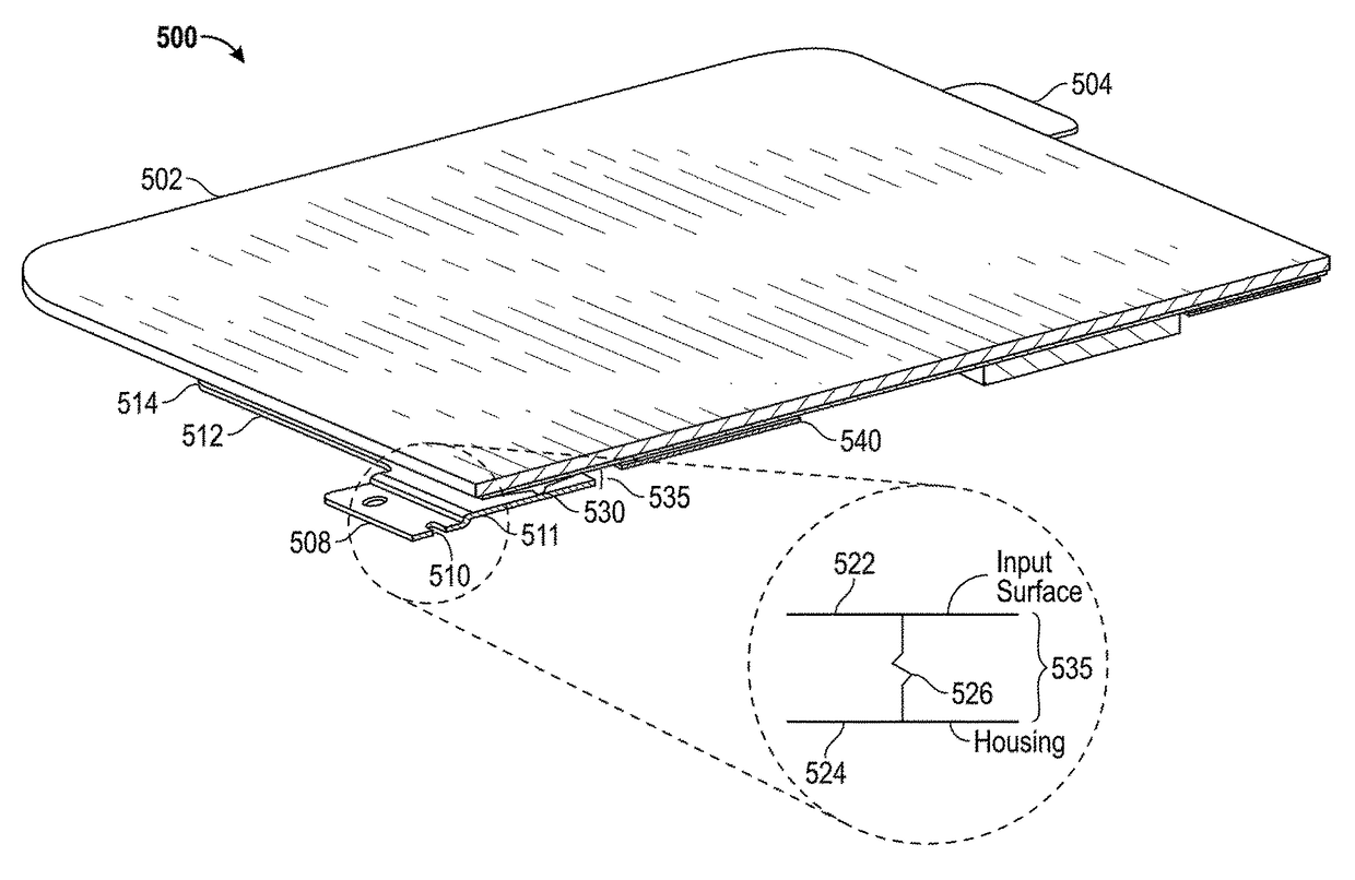
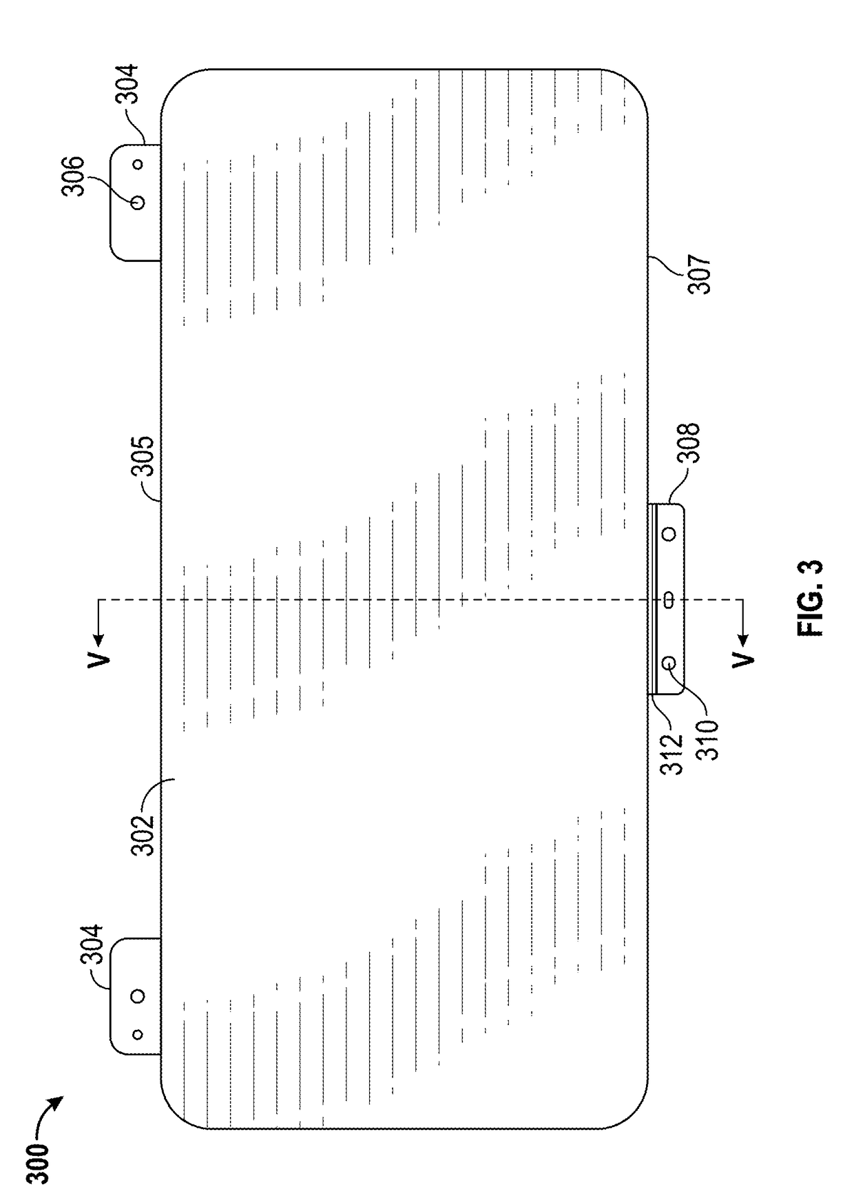
[0021]Various embodiments of the present invention provide input devices and methods that facilitate improved usability by providing an improved hinged input pad which simulates a button press when the input pad surface is deflected downwardly by an input object. By separating or otherwise decoupling the restoring force from the hinge, for example, by placing a passive hinge along a first edge of the input pad a disposing a restoring spring proximate a second edge or segment of the input pad which is not co-extensive with the first edge, hinge fatigue may be reduced.

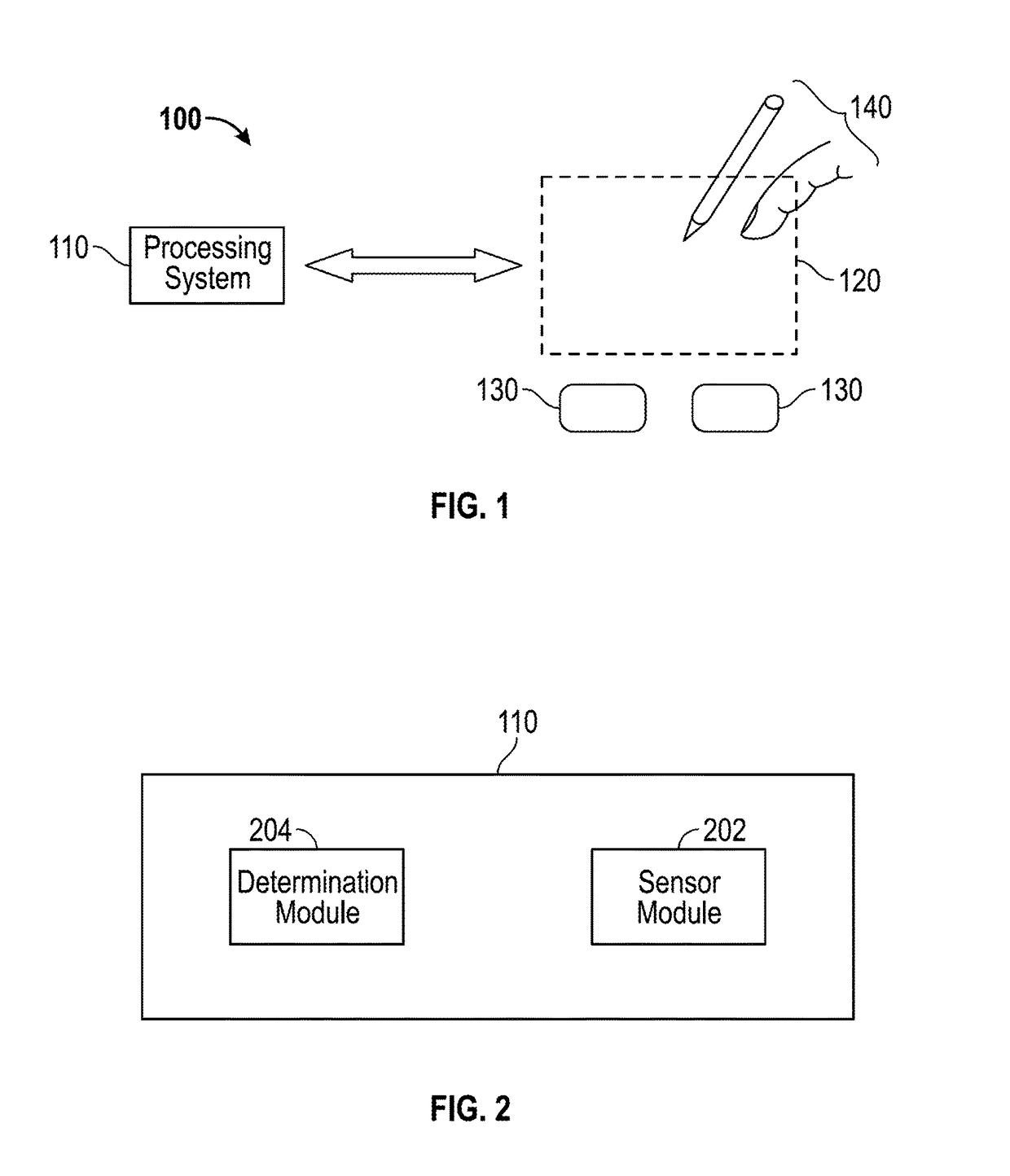
[0022]Turning now to the figures, FIG. 1 is a block diagram of an exemplar...


PUM


Abstract

An input device for use with an electronic system includes a deflectable component having an input surface configured to be touched by input objects and a capacitive sensor layer configured to sense positional information of the input objects. A hinge pivotably mounts a first edge of the deflectable component to the electronic system and facilitates deflection of the deflectable component in response to force applied by an input object to the input surface. A spring mechanism is spaced apart from the hinge and configured to resiliently couple a second edge of the deflectable component to the electronic system and to provide a restoring force responsive to the applied force.

Description

PRIORITY INFORMATION[0001]This application claims priority to U.S. Provisional Patent Application Ser. No. 61 / 679,555, filed Aug. 3, 2012.TECHNICAL FIELD[0002]This invention generally relates to electronic devices, and more specifically relates to sensor devices and using sensor devices for producing user interface inputs.BACKGROUND[0003]Input devices including proximity sensor devices (also commonly called touchpads or touch sensor devices) are widely used in a variety of electronic systems. A proximity sensor device typically includes a sensing region, often demarked by a surface, in which the proximity sensor device determines the presence, location and / or motion of one or more input objects. Proximity sensor devices may be used to provide interfaces for the electronic system. For example, proximity sensor devices are often used as input devices for larger computing systems (such as opaque touchpads integrated in, or peripheral to, notebook or desktop computers). Proximity sensor...

Claims


Application Information

Patent Timeline
Patent Type & Authority Patents(United States)
IPC IPC(8): G06F3/044G06F3/039G06F3/041
CPCG06F3/044G06F3/039G06F3/041G06F3/0393
Inventor TAN, YEH-CHENGCHIU, SU-CHUAN
Owner SYNAPTICS INC
Why Eureka
Try Eureka